Plastic products are everywhere, but designing them isn’t simple. How do engineers balance strength, cost, and production efficiency? This article will uncover the complexities behind the structural design of plastic products. You'll learn key factors, like wall thickness, reinforcing ribs, and more, that make durable, cost-effective plastic parts.
Characteristics and Procedures of Plastic Part Structural Design
Plastic materials offer unique properties and versatile shaping options, setting them apart from conventional engineering materials like steel, copper, aluminum, and wood. This distinctive combination of material composition and formability grants plastics a higher degree of design flexibility compared to their counterparts.
Unique Material Composition and Versatile Shapes
The diverse range of plastic materials, each with its specific properties, allows designers to tailor their choice according to the product's requirements. This variety, coupled with the ability to mold plastics into intricate shapes, enables the creation of complex geometries and functional features that would be challenging or impractical with other materials.
General Procedure for Plastic Part Design
To leverage the advantages of plastics and ensure optimal structural design, it is essential to follow a systematic approach. The general procedure for plastic part design involves several key stages:
Determine functional requirements and appearance of the product:
Draw preliminary design drawings:
Prototyping:
Produce physical prototypes using methods like 3D printing or CNC machining
Evaluate the prototype's functionality, ergonomics, and overall design
Product testing:
Design recalibration and revision:
Analyze test results and identify areas for improvement
Make necessary design adjustments to enhance performance, reliability, or manufacturability
Develop important specifications:
Create detailed specifications for the final product, including dimensions, tolerances, and material grade
Ensure the specifications align with the manufacturing process and quality control standards
Open mold production:
Design and fabricate the injection mold based on the finalized product specifications
Optimize the mold design for efficient material flow, cooling, and ejection
Quality control:
Fundamental Factors in Plastic Product Structural Design
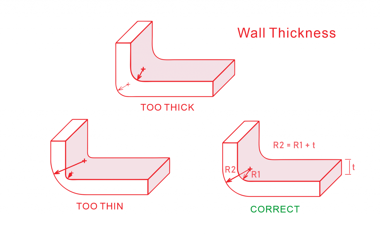
Wall Thickness
Wall thickness plays a crucial role in plastic product design. Proper thickness ensures optimal performance, manufacturability, and cost-effectiveness.
Recommended Wall Thickness Values
| Plastic Material | Minimum (mm) | Small Parts (mm) | Medium Parts (mm) | Large Parts (mm) |
| Nylon | 0.45 | 0.76 | 1.5 | 2.4-3.2 |
| PE | 0.6 | 1.25 | 1.6 | 2.4-3.2 |
| PS | 0.75 | 1.25 | 1.6 | 3.2-5.4 |
| PMMA | 0.8 | 1.5 | 2.2 | 4-6.5 |
| PVC | 1.2 | 1.6 | 1.8 | 3.2-5.8 |
| PP | 0.85 | 1.54 | 1.75 | 2.4-3.2 |
| PC | 0.95 | 1.8 | 2.3 | 3-4.5 |
| POM | 0.8 | 1.4 | 1.6 | 3.2-5.4 |
| ABS | 0.8 | 1 | 2.3 | 3.2-6 |
Factors Affecting Wall Thickness Selection
Plastic material properties
External forces endured
Safety regulations
Reinforcing Ribs
Reinforcing ribs enhance strength without increasing overall wall thickness, prevent product deformation, and improve structural integrity.
Design Guidelines for Reinforcing Ribs
Thickness: 0.5-0.75 times overall wall thickness (recommended: <0.6 times)
Height: Less than 3 times wall thickness
Spacing: Greater than 4 times wall thickness
Aspects of Reinforcement Design Needing Attention
Avoid material accumulation at rib intersections
Maintain perpendicularity to outer walls
Minimize reinforcing ribs on steep slopes
Consider appearance impact of sink marks
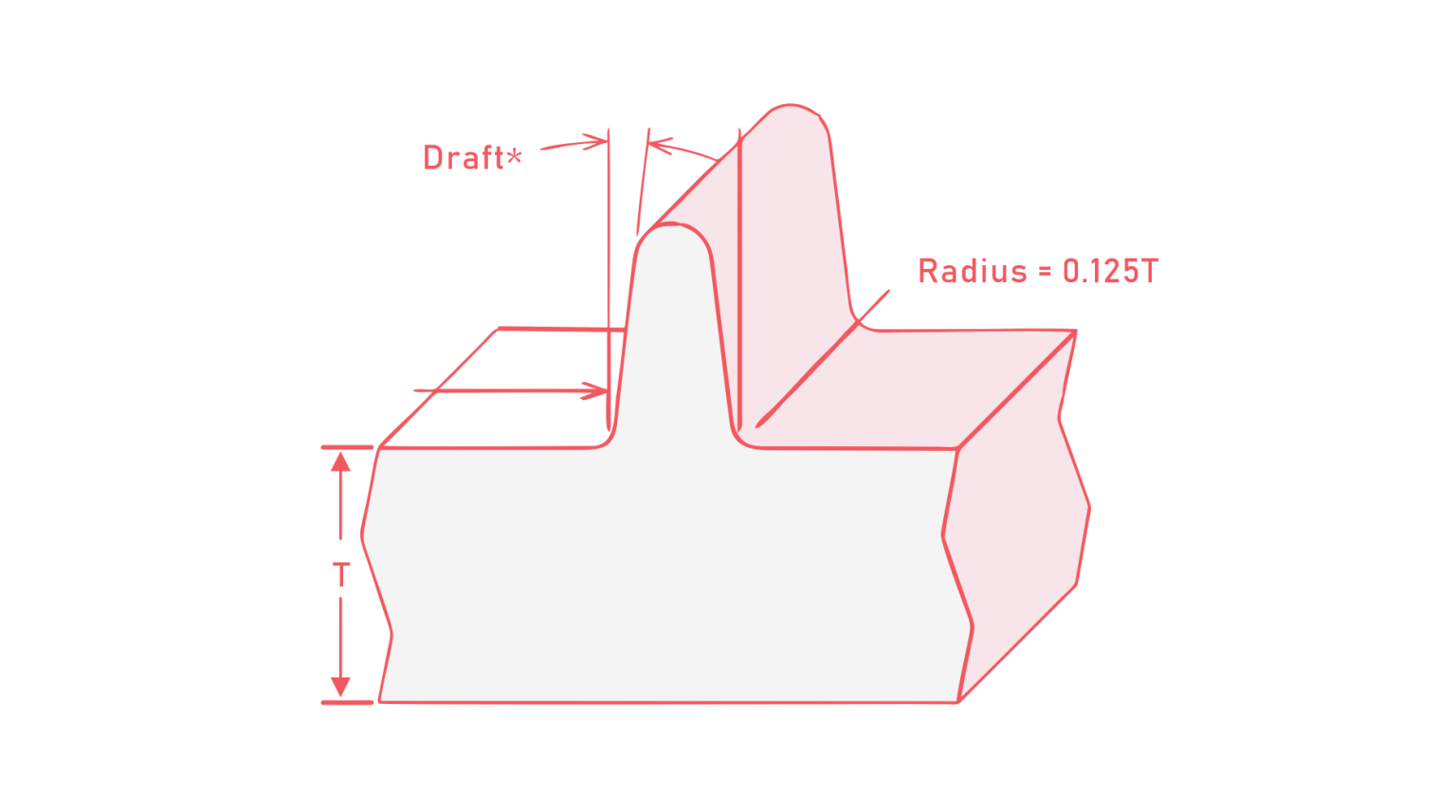
Draft Angles
Draft angles facilitate easy part removal from molds, ensuring smooth production and high-quality parts.
Recommended Draft Angles for Different Materials
| Material | Mold Core | Mold Cavity |
| ABS | 35'-1° | 40'-1°20' |
| PS | 30'-1° | 35'-1°30' |
| PC | 30'-50' | 35'-1° |
| PP | 25'-50' | 30'-1° |
| PE | 20'-45' | 25'-45' |
| PMMA | 30'-1° | 35'-1°30' |
| POM | 30'-1° | 35'-1°30' |
| PA | 20'-40' | 25'-40' |
| HPVC | 50'-1°45' | 50'-2° |
| SPV | 25'-50' | 30'-1° |
| CP | 20'-45' | 25'-45' |
Aspects of Draft Angle Selection Needing Attention
Choose smaller angles for glossy surfaces and high-precision parts
Use larger angles for parts with high shrinkage rates
Increase draft for transparent parts to prevent scratches
Adjust angle based on texture depth for textured surfaces
R Corners (Rounded Corners)
Rounded corners reduce stress concentration, facilitate plastic flow, and ease demolding.
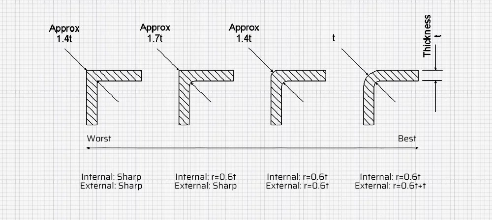
Design Guidelines for R Corners
Internal corner radius: 0.50 to 1.50 times material thickness
Minimum radius: 0.30mm
Maintain uniform wall thickness when designing rounded corners
Avoid rounded corners on mold parting surfaces
Use minimum 0.30mm radius for edges to prevent scratching
Holes
Holes serve various functions in plastic products and require careful design consideration.
Design Requirements for Holes
Relationship Between Hole Diameter and Depth
Design Considerations for Special Hole Types
Step holes: Use multiple coaxially connected holes of different diameters
Angled holes: Align axis with mold opening direction when possible
Side holes and indentations: Consider core pulling structures or design improvements
Bosses
Bosses provide assembly points, support other parts, and enhance structural integrity.
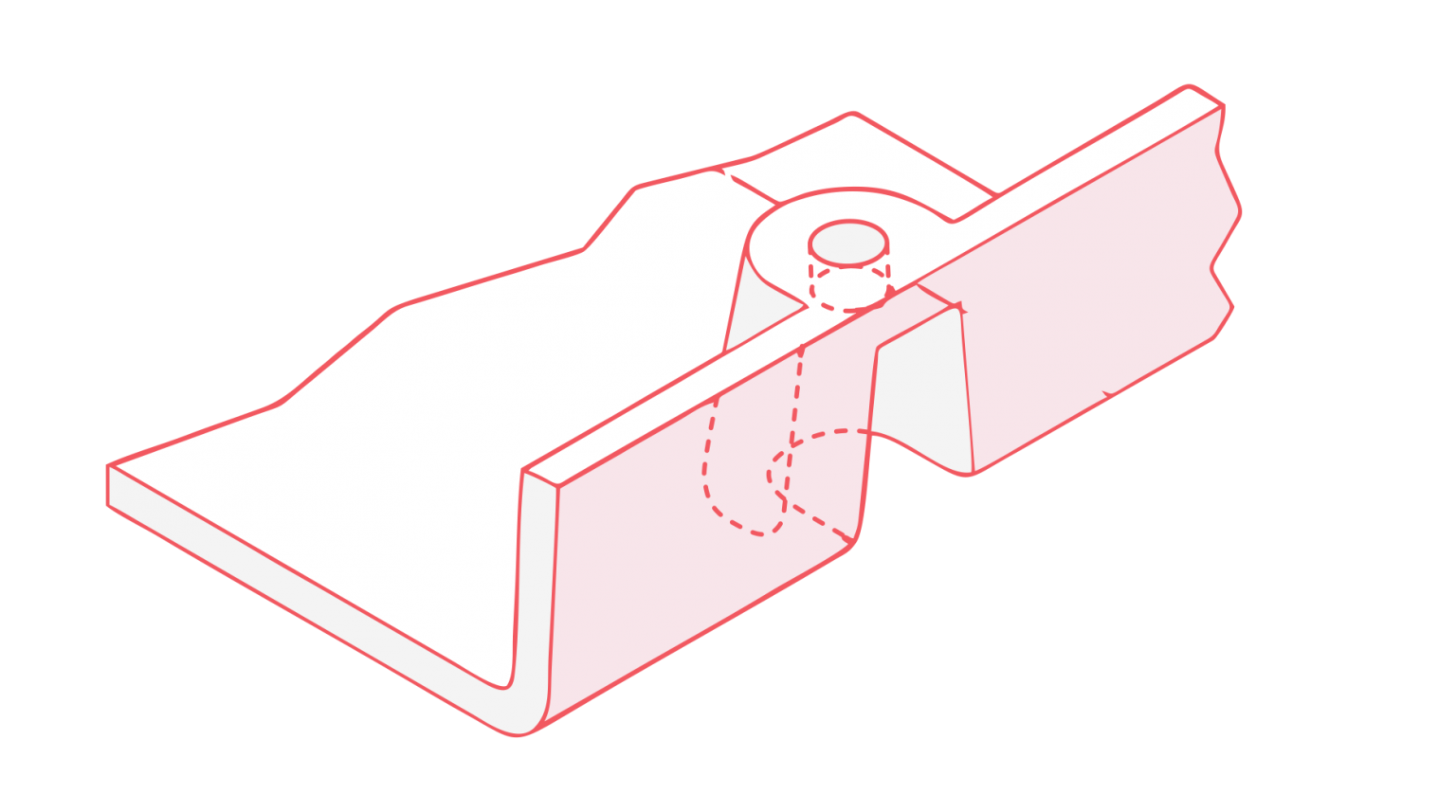
Basic Design Guidelines for Bosses
Height: ≤ 2.5 times boss diameter
Use reinforcement ribs or attach to outer walls when possible
Design for smooth plastic flow and easy demolding
Design Points for Different Materials
ABS: Outer diameter ≈ 2x inner diameter; use beveled ribs for strengthening
PBT: Base design on rib concept; connect to sidewalls when possible
PC: Interlock side bosses with ribs; use for assembly and support
PS: Add ribs for strengthening; connect to sidewalls when nearby
PSU: Outer diameter ≈ 2x inner diameter; height ≤ 2x outer diameter
Inserts
Inserts enhance functionality, provide decorative elements, and improve assembly options in plastic parts.
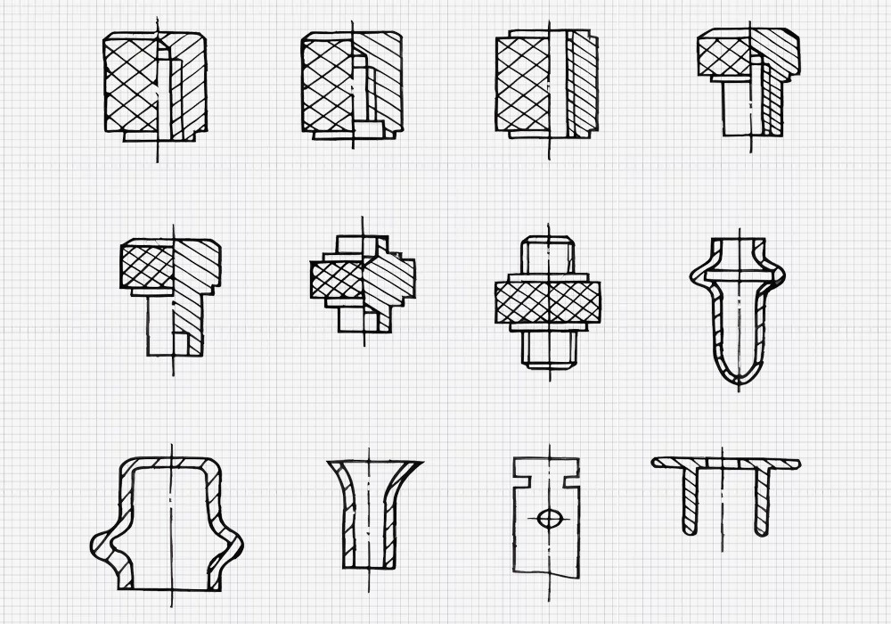
Shape and Structural Requirements for Inserts
Manufacturability: Compatible with cutting or stamping processes
Mechanical strength: Sufficient material and dimensions
Bonding strength: Adequate surface features for secure attachment
Positioning: Cylindrical extending portions for easy mold placement
Flash prevention: Include sealing boss structures
Post-processing: Design for secondary operations (threading, cutting, flanging)
Design Considerations When Using Inserts
Ensure precise positioning within molds
Create strong connections with molded parts
Prevent plastic leakage around inserts
Consider thermal expansion differences between insert and plastic material
Product Surface Texture and Text/Pattern Design
Surface Textures for Plastic Products
Plastic product surfaces can be designed with various textures to enhance aesthetics, functionality, and user experience. Common surface textures include:
Smooth
Spark-etched
Patterned etched
Engraved
Smooth Surfaces
Smooth surfaces result from polished mold surfaces. They offer:
Spark-Etched Surfaces
Created through copper EDM processing of the mold cavity, spark-etched surfaces provide:
Patterned Etched Surfaces
These surfaces feature various patterns etched into the mold cavity, offering:
Engraved Surfaces
Engraved surfaces are created by directly machining patterns into the mold, allowing for:
Draft Angle Considerations for Textured Surfaces
When designing textured surfaces, consider increasing draft angles to facilitate part ejection:
| Texture Depth | Recommended Additional Draft Angle |
| 0.025 mm | 1° |
| 0.050 mm | 2° |
| 0.075 mm | 3° |
| > 0.100 mm | 4-5° |
Text and Pattern Design
Plastic products often incorporate text and patterns for branding, instructions, or decorative purposes. These elements can be either raised or recessed.
Raised vs. Recessed Surfaces
Recommendation: Use raised surfaces for text and patterns when possible.
Benefits of raised surfaces:
For designs requiring flush or recessed features:
Create a recessed area
Raise text or pattern within the recess
Maintain overall flush appearance while simplifying mold design
Text and Pattern Dimensions
| Feature | Recommended Dimension |
| Height/Depth | 0.15 - 0.30 mm (raised) |
| 0.15 - 0.25 mm (recessed) |
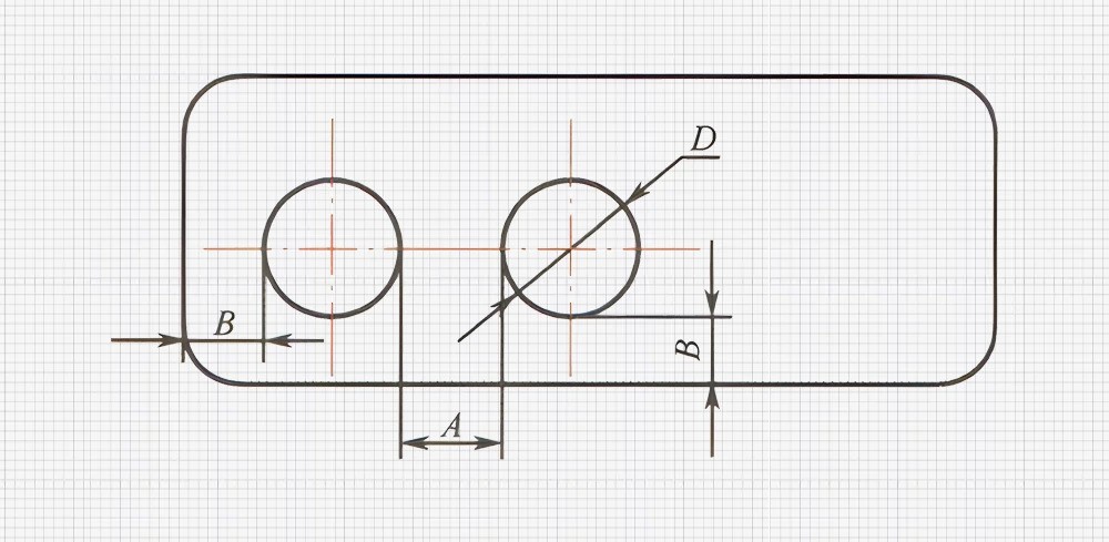
Text Size Specifications
Follow these guidelines for optimal text design:
Stroke width (A): ≥ 0.25 mm
Spacing between characters (B): ≥ 0.40 mm
Distance from characters to edge (C, D): ≥ 0.60 mm
Additional Text/Pattern Design Considerations
Avoid sharp angles in text or patterns
Ensure size is conducive to molding process
Consider the impact of text/pattern on overall part strength
Evaluate the effect of text/pattern on material flow during molding
Additional Structural Design Considerations
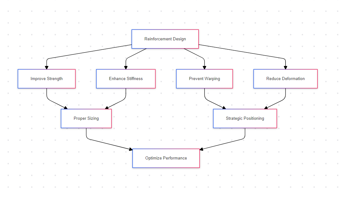
Reinforcement Structure Design Principles
Reinforcement structures play a crucial role in enhancing the overall performance of plastic products. They significantly improve strength, stiffness, and dimensional stability.
Key Objectives of Reinforcement Design:
Strength enhancement
Stiffness improvement
Warping prevention
Deformation reduction
Proper Positioning and Sizing of Reinforcements:
Wall thickness: 0.4-0.6 times main body thickness
Spacing: > 4 times main body thickness
Height: < 3 times main body thickness
Screw column reinforcement: At least 1.0mm below column surface
General reinforcement: Minimum 1.0mm below part surface or parting line
Advanced Reinforcement Techniques:
Misaligned reinforcement bars to prevent material buildup
Hollow structures at reinforcement intersections
Tension-based designs for slender reinforcements
Avoiding Stress Concentration
Stress concentration can significantly impact the structural integrity and longevity of plastic products. Proper design techniques can mitigate these issues.
Importance of Avoiding Sharp Corners:
Measures to Reduce Stress Concentration:
Chamfers
Rounded corners
Gentle slopes for transitions
Inward hollowing at sharp corners
| Technique | Description | Benefit |
| Chamfers | Beveled edges | Gradual stress distribution |
| Rounded corners | Curved transitions | Eliminates sharp stress points |
| Gentle slopes | Gradual thickness changes | Even stress distribution |
| Inward hollowing | Material removal at corners | Localized stress reduction |
Designing Suitable Draft Angles
Draft angles are essential for successful part ejection from molds. They significantly impact part quality and production efficiency.
Principles for Determining Draft Angles:
Use whole number angles (e.g., 0.5°, 1°, 1.5°)
Exterior angles > interior angles
Maximize angles without compromising appearance
Factors Influencing Draft Angle Size:
Part depth
Surface finish
Material shrinkage rate
Texture depth
Draft Angle Design Points for Different Materials:
| Material | Recommended Draft Angle Range |
| ABS | 0.5° - 1° |
| PC | 1° - 1.5° |
| PP | 0.5° - 1° |
| PS | 0.5° - 1° |
| PET | 1° - 1.5° |
Structural Design from Mold Structure Perspective
Efficient mold design is crucial for successful plastic part production. Consider these aspects to optimize both part and mold design.
Avoiding Complex Structures:
Simplify part geometry
Reduce undercuts
Minimize side actions
Avoiding Internal Cutting Structures:
Considering Lateral Release Requirements:
Allow sufficient space for slider movement
Design appropriate shut-off surfaces
Optimize part orientation in the mold
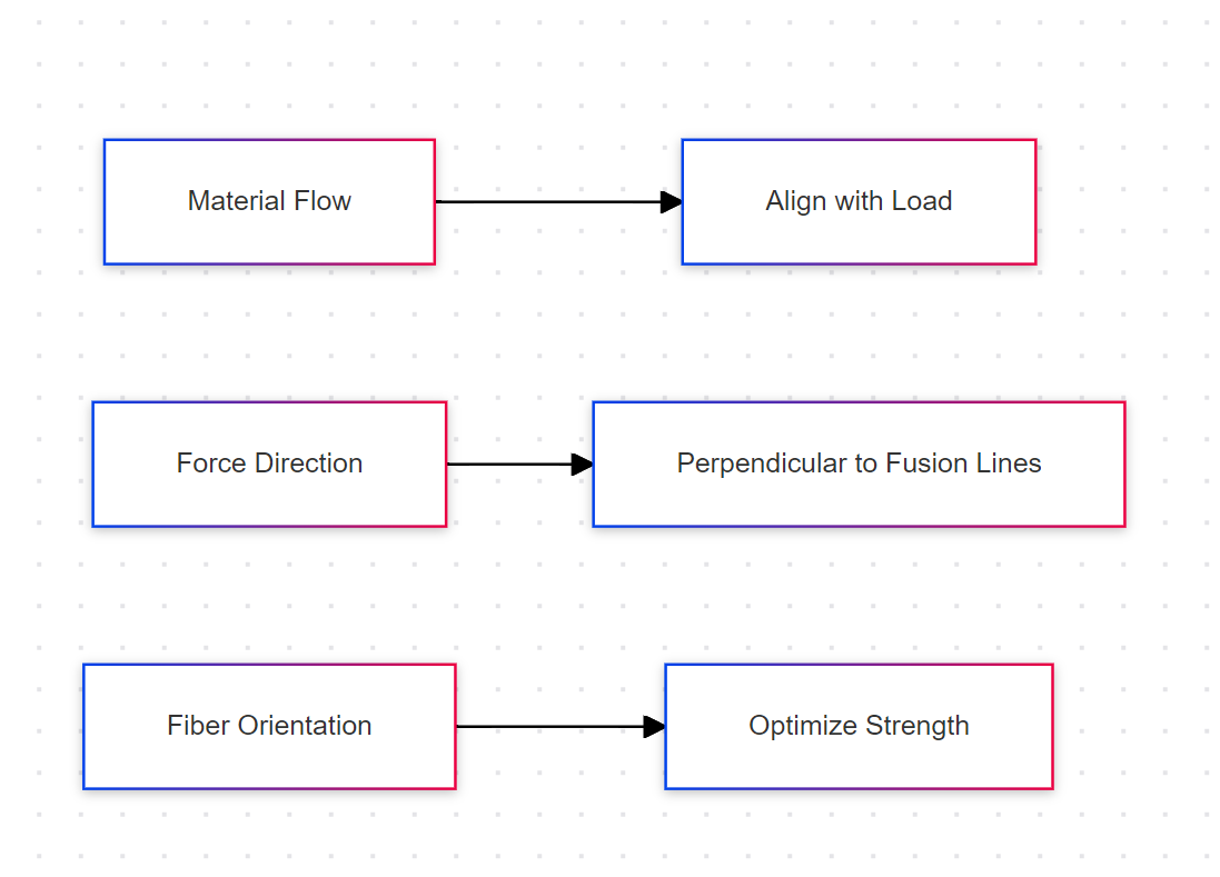
Designing for Non-Isotropic Characteristics of Plastics
Many plastics exhibit non-isotropic properties, requiring special design considerations to maximize performance.
Aligning Material Flow Direction with Load-Bearing Direction:
Force Direction Relative to Fusion Lines:
Structural Design from Assembly Perspective
Effective assembly design ensures product functionality, longevity, and ease of manufacture.
Avoiding Large Sizes with Small Tolerances:
Bonding Interface Design:
Prioritize shear force over tearing tension
Increase bonding surface area
Consider chemical compatibility of adhesives
Bolt Connection Considerations for Plastic Parts:
Use inserts for high-stress connections
Design appropriate boss structures
Consider thermal expansion differences
Summary
In plastic product design, key structural factors like wall thickness, reinforcing ribs, and draft angles are essential for durability and performance. It's crucial to consider material properties, mold structure, and assembly needs throughout the process. Proper structural design not only enhances product functionality but also reduces defects and manufacturing costs. By focusing on these design elements, manufacturers can ensure high-quality, cost-effective plastic parts that meet both functional and aesthetic requirements.


