Plastic injection molding is a vital manufacturing process used to create many everyday items. But what makes it efficient? The feed system plays a critical role. A well-designed feed system ensures quality, reduces waste, and boosts productivity. In this post, you'll learn about the components of the feed system, its design principles, and how it affects part quality and cost-effectiveness.
What is a Feeding System in Injection Molding?
A feeding system in injection molding is crucial to ensure that molten plastic flows efficiently into the mold cavity. It consists of channels that guide the molten material from the machine nozzle to the mold. This system includes key components such as the sprue, runner, and gate, each serving a unique function.
The Role of the Feeding System
The feeding system has a vital job. It delivers molten plastic into the mold cavity under precise conditions of pressure and temperature. If designed well, it can reduce defects like weld lines and air bubbles, and ensure the even filling of the mold. Proper flow paths also maintain dimensional accuracy.
Importance of a Well-Designed Feeding System
A properly designed feed system boosts efficiency and product quality. By minimizing material waste and balancing the filling process, the system lowers costs. It also prevents common molding defects such as shrinkage, flash, and short shots, which could otherwise affect the part's appearance and structural integrity. Ultimately, a well-structured feed system can shorten cycle times and improve productivity.
Components of the Feeding System
The feeding system in an injection mold consists of several key components. Let's take a closer look at each one.
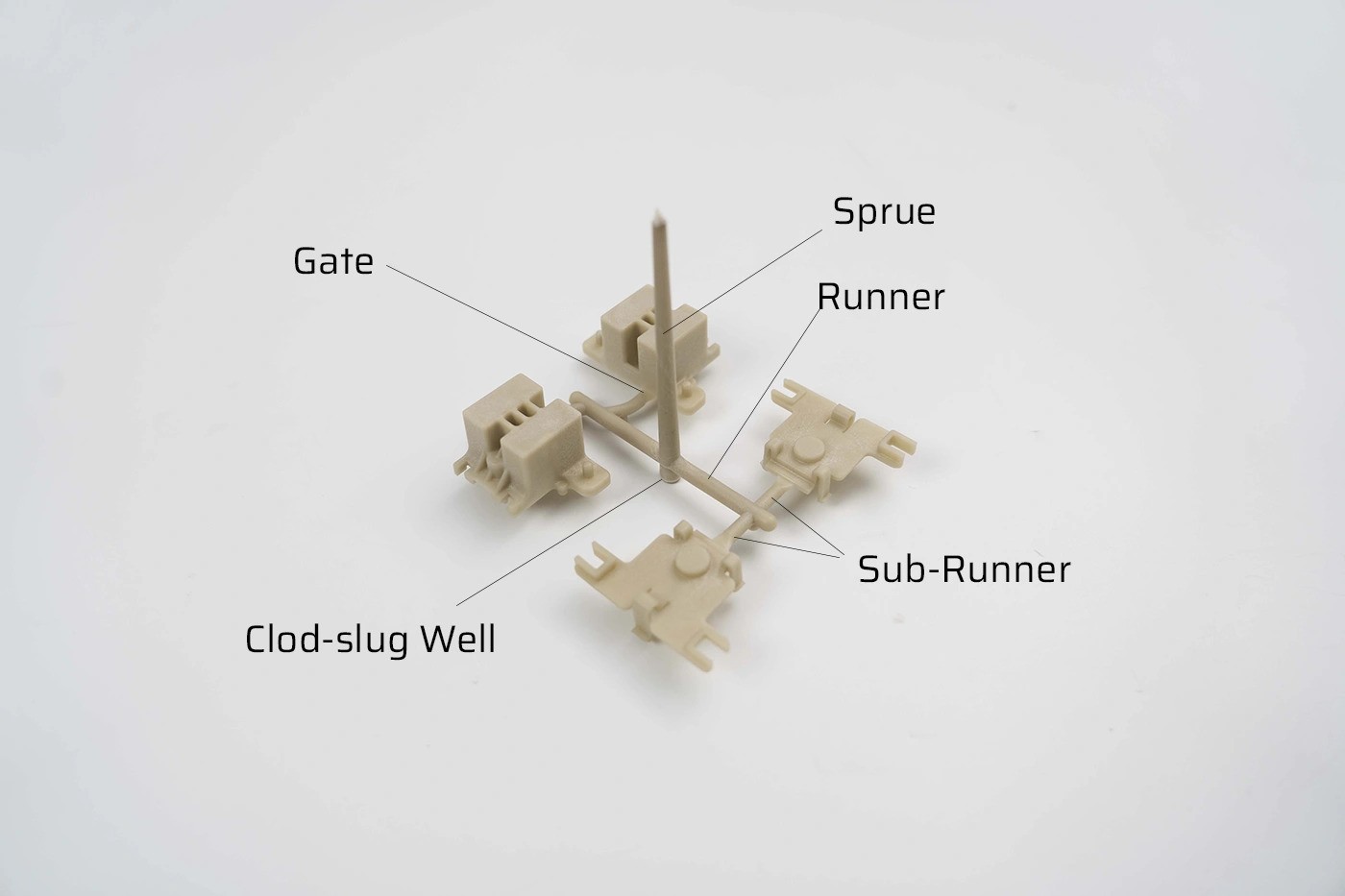
Sprue
The sprue is the initial channel where molten plastic enters the mold. It's responsible for conveying the plastic melt from the injection machine's nozzle to the runners.
When designing the sprue, consider:
Sprue length and diameter
Taper angle for easy part removal
Smooth transitions to runners
Runner and Sub-runner
Runners are channels that transport molten plastic from the sprue to the gates. Sub-runners branch off from the main runner to distribute the melt to multiple cavities.
They play a crucial role in:
Guiding the melt to the desired locations
Ensuring even distribution of plastic
Maintaining pressure and temperature
Gate
Gates are the entry points where molten plastic flows into the mold cavity. They control the flow and help pack the cavity with melt.
Common types of gates include:
Tab gate
Edge gate
Hot tip gate
Tunnel gate
The type of gate used depends on factors like part geometry, material, and desired appearance.
Cold Slug Well
Cold slug wells, also known as cold material traps, are located at the end of the runner system. They collect the cold material that first enters the mold, which can contain impurities or degraded plastic.
By trapping this cold material, they prevent it from entering the mold cavity and causing defects like:
Including cold slug wells in your feeding system design helps ensure the quality of your molded parts.
Types of Feed Systems in Injection Molding
Choosing the right feed system is crucial in injection molding. Different systems can affect product quality, cost, and production efficiency. The three main types are cold runner systems, hot runner systems, and insulated runner systems. Each has its strengths and weaknesses.
Cold Runner Systems
Cold runner systems are the traditional method of injection molding. They use unheated runners to transport molten plastic to the mold cavity.
Characteristics and Classification
Cold runners can be classified into two main types: side gate systems and point gate systems. In both, the plastic solidifies in the runner, requiring additional processes to remove excess material.
Advantages
Simple to use and maintain
Works with a wide range of materials
Lower tooling cost than hot runner systems
Disadvantages
Creates waste in the form of runners, which must be recycled or discarded
Longer cycle times due to the cooling of runners
Not suitable for complex or large-volume production
Visible gate marks on the final product
Hot Runner Systems
Hot runner systems, unlike cold runners, maintain the plastic in a molten state throughout the process, eliminating the need for material removal after molding.
Structure and Design Principles
Hot runners use heated manifolds and hot nozzles to deliver plastic directly into the mold cavities. This design ensures consistent temperature and flow throughout the injection process.
Pros
Reduces material waste as runners remain molten
Shortens cycle times by avoiding cooling and removal steps
Ideal for complex parts and high-volume production
Cons
High initial cost for tooling and maintenance
Difficult to clean and maintain, especially for heat-sensitive materials
Not suitable for all materials
You can also learn more about both in our Hot vs Cold Runner.
Insulated Runner Systems
Insulated runner systems are a hybrid between cold and hot runner systems. They maintain a layer of molten plastic within a solidified outer layer to insulate the material.
Working Principle
Using cartridge heaters or other forms of external heating, insulated runners keep the internal plastic molten while the outer layer cools. This reduces waste, similar to hot runner systems, but at a lower cost.
Benefits
Less expensive than hot runner systems
Easier material and color changes
Reduced material waste compared to cold runner systems
Suitable for small to medium production runs
Limitations
Not ideal for demanding engineering-grade plastics
Longer cycle times compared to hot runner systems
Requires careful design and optimization
Design Principles of the Feeding System in Injection Molds
A well-designed feeding system in injection molding is essential for high-quality products and efficient production. The following principles guide its design to ensure optimal performance.
Ensuring Product Quality
To ensure the quality of your molded parts, consider these factors when designing the feeding system:
Avoid weld marks by optimizing gate location and size
Prevent overpacking and insufficient packing pressure by balancing the flow
Minimize defects like short shots, flash, air trapping, and warpage
Additionally, aim for:
Optimizing Production Efficiency
To optimize production efficiency, focus on these aspects of feeding system design:
Minimize post-processing requirements
Shorten the molding cycle
Improve overall production efficiency
Considering Plastic Material Properties
Different plastic materials have unique flow characteristics. When designing the feeding system, consider:
Select flow channel dimensions that accommodate the specific properties of the plastic material being used.
Facilitating Solidification Residue Removal
To ensure easy removal of solidified material from the feeding system:
Design for convenient and reliable residue removal
Choose appropriate ejection positions
Proper design for residue removal helps maintain part quality and reduces cycle times.
Minimizing Waste and Mold Size
To minimize waste and mold size:
Reduce the cross-section and length of the feeding system
Minimize plastic usage and mold size
Minimizing waste and mold size helps reduce material costs and improves sustainability.
Reducing Heat Dissipation and Pressure Drop
To reduce heat dissipation and pressure drop in the feeding system:
Keep flow paths short and ensure adequate cross-sectional area
Avoid sharp bends and sudden changes in flow direction
Maintain low surface roughness in flow paths
Consider multi-gating to reduce pressure drop and required injection pressure
By minimizing heat loss and pressure drop, you can improve the efficiency of the injection molding process.
Achieving Simultaneous Filling
In multi-cavity molds, it's important to achieve simultaneous filling of all cavities. To do this:
Ensure simultaneous material entry into each cavity
Maintain equal pressure at each cavity entrance
Achieving simultaneous filling helps ensure consistent part quality and reduces cycle times.
Feeding System Design Steps
Designing a feeding system for an injection mold involves several key steps. Each step plays a crucial role in ensuring the quality and efficiency of the molding process.
Determine the feeding method
Decide between a side gate, point gate, or runner-less system
Consider the product structure, size, and appearance requirements
Choose a feeding method that ensures proper filling and minimizes defects
Design the gate
Select the appropriate gate type (e.g., tab, edge, hot tip, tunnel)
Determine the gate location, size, and quantity based on the product design
Ensure the gate design facilitates easy removal and minimizes visible marks
Main runner dimensions and location
Calculate the main runner diameter based on the shot weight and material
Determine the main runner location considering the mold layout and gating points
Ensure adequate cross-sectional area to minimize pressure drop and heat loss
Sub-runner design
Determine the sub-runner layout based on the number and location of cavities
Select the appropriate sub-runner shape (e.g., circular, trapezoidal, half-round)
Size the sub-runners to ensure balanced flow and minimize pressure drop
Assistant runner design
Evaluate the need for assistant runners based on the product geometry and gating
Design assistant runners to improve flow balance and cavity filling
Determine the shape and size of assistant runners for optimal performance
Cold slug well design
Identify locations prone to cold material accumulation
Incorporate cold slug wells to trap cold material and prevent it from entering the cavity
Size the cold slug wells based on the runner system volume and material properties
Conclusion
A well-designed feeding system is crucial for producing high-quality injection molded parts efficiently. It ensures proper filling, minimizes defects, and reduces waste.
Collaborative efforts between OEMs and contract manufacturers are essential for optimizing feeding system design. By working together, they can leverage their expertise to create robust, cost-effective solutions that meet the unique requirements of each project.
Team Mfg has more than ten years of experience in injection molding services. Thousands of customers have achieved success because of us. If you have injection molding needs, please contact us immediately.


