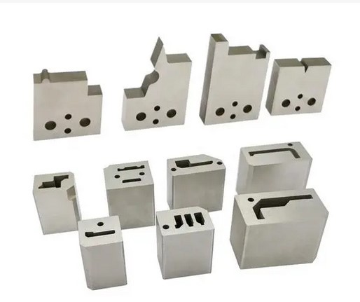
Molding metal inserts into a part, often considered a last resort because of the difficulties associated with it, may pay off with some outstanding advantages when adequate safeguards are taken in the design stage.

Instead of a mold that produces a final part using two separate shots like overmolding, insert molding generally consists of a preformed part—often metal—that is loaded into a mold, where it is then overmolded with plastic to create a part with improved functional or mechanical properties.
Advantages
The three principal reasons for using metal inserts are:
To provide threads that are serviceable under continuous stress or permit frequent part disassembly.
To meet close tolerances on female threads.
To provide a permanent means of attaching two high-load-bearing parts, such as a gear to a shaft.
One way insert molding is used is with threaded inserts, which reinforce the mechanical properties of plastic parts’ ability to be fastened together, especially over repeated assembly. Bushings and sleeves are another great way to increase part durability for mating components that need more abrasion resistance due to moving parts.
Materials:
ABS
Acetal
HDPE
LCP
PEI
PMMA
Polycarbonate
Polypropylene
PPA
PPS
PS
PS
PSU
TPE
TPU
PEEK
Liquid Silicone Rubber
Insert Molding Design Guide
Inserts should be rounded, or have rounded knurling, and there should be no sharp corners. An undercut should be provided for pull-out strength.
The insert should protrude at least .4 mm (.016 inch) into the mold cavity. Depth of molding beneath it should equal at least one-sixth of the insert’s diameter to avoid sink marks (see drawing, above right).
Boss diameter should be 1.5 times the insert diameter except for inserts with a diameter greater than 12.9 mm (.5 inch; see drawing, above left). For the latter, the boss wall should be derived with the overall part thickness and specific grade of material in mind.
Keep the metal insert small relative to the plastic surrounding it.
Toughened grades of resin should be considered. These have higher elongation than standard grades and a greater resistance to cracking.
Inserts molding should be preheated before molding. This minimizes post-mold shrinkage, pre-expands the insert, and improves weldline strength.
Conduct a thorough end-use test program to detect problems in the prototype stage of development. Testing should include temperature cycling over the range to which the application may be exposed.


