Clamping force is crucial for producing high-quality molded products. But how much force is enough? In injection molding, precise clamping force ensures the mold stays closed during the process, preventing defects like flash or damage. In this post, you’ll learn the role of clamping force, how it affects production, and methods to calculate it accurately for the best results.
What is Clamping Force in Injection Molding?
Clamping force is the power that keeps mold halves together during injection. It's like a giant vise grip, holding everything in place.
This force comes from the machine's hydraulic system or electric motors. They push the mold halves together with incredible strength.
Simply put, clamping force is the pressure applied to keep molds closed. It's measured in tons or metric tons.
Think of it as the machine's muscle power. The stronger the clamp, the more pressure it can handle.
Role of Clamping Force in the Injection Molding Process
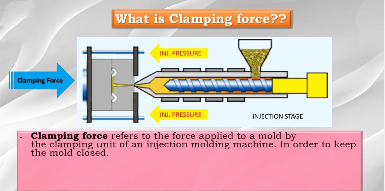
The clamping unit is a critical component of an injection molding machine. It consists of a fixed platen and a moving platen, which hold the two halves of the mold. The clamping mechanism, usually hydraulic or electric, generates the force needed to keep the mold closed during the injection process.
Here's how clamping force is applied during a typical molding cycle:
The mold closes, and the clamping unit applies an initial clamping force to keep the mold halves together.
The injection unit melts the plastic and injects it into the mold cavity under high pressure.
As the molten plastic fills the cavity, it generates a counter-pressure that tries to push the mold halves apart.
The clamping unit maintains the clamping force to resist this counter-pressure and keep the mold closed.
Once the plastic cools and solidifies, the clamping unit opens the mold, and the part is ejected.
Without proper clamping force, parts could have defects like:
Importance of Maintaining Proper Clamping Force
Getting the clamping force right is crucial for quality and efficiency,
Proper clamping force ensures:
High-quality parts
Longer mold life
Efficient energy use
Faster cycle times
Reduced material waste
Factors Affecting Clamping Force in Injection Molding
Several key factors determine the clamping force needed in injection molding, ensuring the mold stays closed during the process and preventing defects. These factors include the projected area, cavity pressure, material properties, mold design, and processing conditions.
Projected Area and Its Impact on Clamping Force
Definition of Projected Area:
The projected area refers to the largest surface of the molded part, as viewed from the clamping direction. It represents the part’s exposure to the internal forces generated by molten plastic during injection.
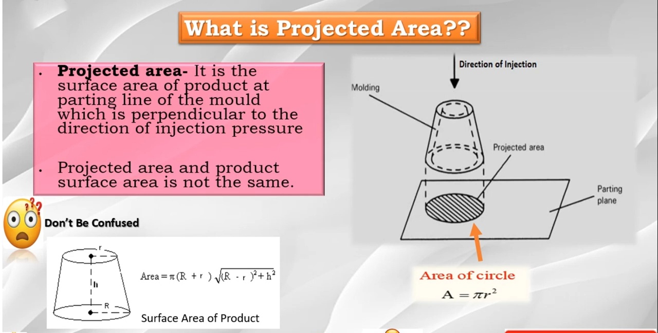
How to Determine the Projected Area:
For square parts, calculate the area by multiplying the length by the width. For circular parts, use the formula:
The total projected area increases with the number of cavities in the mold.
Relationship Between Projected Area and Clamping Force:
A larger projected area requires more clamping force to prevent the mold from opening during injection. This is because a larger surface area results in greater internal pressure.
Examples:
Part Wall Thickness: Thin walls increase internal pressure, requiring higher clamping force to hold the mold closed.
Flow Length-to-Thickness Ratio: The higher the ratio, the more pressure builds up inside the cavity, increasing the need for clamping force.
Cavity Pressure and Its Influence on Clamping Force
Definition of Cavity Pressure:
Cavity pressure is the internal pressure exerted by the molten plastic as it fills the mold. It depends on material properties, injection speed, and part geometry.
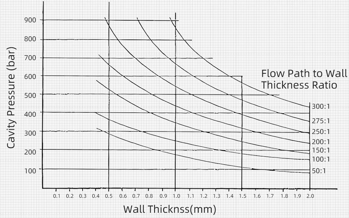
relationship between cavity pressure wall thickness and path to thickness ratio
Factors Influencing Cavity Pressure:
Wall Thickness: Thin-walled parts lead to higher cavity pressure, while thicker walls reduce pressure.
Injection Speed: Faster injection speeds result in higher cavity pressure inside the mold.
Material Viscosity: Higher-viscosity plastics generate more resistance, increasing the pressure.
How Cavity Pressure Affects Clamping Force Requirements:
As cavity pressure rises, more clamping force is needed to prevent the mold from opening. If the clamping force is too low, mold separation can occur, leading to defects like flash. Properly calculating the cavity pressure helps determine the appropriate clamping force.
Material Properties and Mold Design
Material Properties:
Viscosity: High-viscosity plastics flow less easily, requiring more force.
Density: Denser materials need higher pressures to fill the mold properly.
Mold Design Factors:
Injection Speed and Temperature
Both injection speed and mold temperature affect how plastic flows and solidifies. Faster injection speeds and lower mold temperatures generally increase internal cavity pressure, thus requiring more clamping force to keep the mold closed during the process.
How to Calculate Clamping Force in Injection Molding
Calculating clamping force isn't rocket science, but it's crucial for successful molding. Let's explore various methods, from basic to advanced.
1. Basic Formula
The fundamental equation for clamping force is:
Clamping Force = Projected Area × Cavity Pressure
Explanation of components:
Multiply these, and you've got your estimated clamping force.
2. Empirical Formulas
Sometimes, quick estimates are needed. That's where empirical methods come in handy.
Kp method
Clamping Force (T) = Kp × Projected Area (cm²)
Kp values vary by material:
PE/PP: 0.32
ABS: 0.30-0.48
PA/POM: 0.64-0.72
350 bar method
Clamping Force (T) = (350 × Projected Area (cm²)) / 1000
This method assumes a standard cavity pressure of 350 bar.
Pros and cons of empirical methods
Pros:
Cons:
3. Advanced Calculation Methods
For more precise calculations, consider material characteristics and processing conditions.
Thermoplastic flow characteristics grouping
| Grade | Thermoplastic Materials | Flow Coefficients |
| 1 | GPPS, HIPS, LDPE, LLDPE, MDPE, HDPE, PP, PP-EPDM | ×1.0 |
| 2 | PA6, PA66, PA11/12, PBT, PETP | ×1.30~1.35 |
| 3 | CA, CAB, CAP, CP, EVA, PUR/TPU, PPVC | ×1.35~1.45 |
| 4 | ABS, ASA, SAN, MBS, POM, BDS, PPS, PPO-M | ×1.45~1.55 |
| 5 | PMMA, PC/ABS, PC/PBT | ×1.55~1.70 |
| 6 | PC, PEI, UPVC, PEEK, PSU | ×1.70~1.90 |
Table of flow coefficients of common thermoplastic materials
Step-by-step calculation process
Determine projected area
Calculate cavity pressure using flow length-to-thickness ratio
Apply material group multiplication constant
Multiply area by adjusted pressure
Example: For a PC part with 380cm² area and 160 bar base pressure:
Clamping Force = 380cm² × (160 bar × 1.9) = 115.5 tons
4. CAE Software Calculations
For complex parts or high-precision needs, CAE software is invaluable.
Introduction to Moldflow and similar software
These programs simulate the injection molding process. They predict cavity pressures and clamping forces with high accuracy.
Benefits of using CAE
Accounts for complex geometries
Considers material properties and processing conditions
Provides visual pressure distribution maps
Helps optimize mold design and processing parameters
Example: Clamping Force Calculation for a Polycarbonate Lamp Holder
Let's dive into a real-world example. We'll calculate the clamping force for a polycarbonate lamp holder.
Understanding the Example
Our lamp holder has these specifications:
Outer diameter: 220mm
Wall thickness: 1.9-2.1mm
Material: Polycarbonate (PC)
Design: Pin-shaped center gate
Longest flow path: 200mm
Polycarbonate is known for its high viscosity. This means it'll need more pressure to fill the mold.
Step-by-Step Calculation
Let's break down the process:
Calculate the flow length to wall thickness ratio:
Ratio = Longest flow path / Thinnest wall= 200mm / 1.9mm= 105:1
Determine base cavity pressure:
Adjust for material properties:
PC is in viscosity group 6
Multiplication factor: 1.9
Adjusted pressure = 160 bar * 1.9 = 304 bar
Calculate projected area:
Area = π * (diameter/2)⊃2;= 3.14 * (22/2)⊃2; = 380 cm²
Compute clamping force:
Force = Pressure * Area= 304 bar * 380 cm²= 115,520 kg= 115.5 tons
Adjustments for Safety and Efficiency
For safety, we round up to the next available machine size. A 120-ton machine would be suitable.
Consider these factors for efficiency:
Start with 115.5 tons and adjust based on part quality
Monitor for flash or short shots
Gradually reduce force if possible without compromising quality
Injection Molding Machine Selection and Clamping Force Matching
Choosing the right injection molding machine is crucial for success. It's not just about clamping force - several factors come into play.
Relationship between Clamping Force and Machine Parameters
Clamping force isn't isolated. It's closely tied to other machine specifications:
Injection Capacity:
Screw Size:
Mold Opening Stroke:
Tie Bar Spacing:
Reference Ranges for Common Plastic Products
Clamping force needs vary widely. Here's a general guide:
| Product | Material | Projected Area (cm²) | Required Clamping Force (Tons) |
| Thin-walled containers | Polypropylene (PP) | 500 cm² | 150-200 Tons |
| Automotive components | ABS | 1,000 cm² | 300-350 Tons |
| Electronic housings | Polycarbonate (PC) | 700 cm² | 200-250 Tons |
| Bottle caps | HDPE | 300 cm² | 90-120 Tons |
The table above provides a rough guide for matching product types with the necessary clamping force. These figures can vary depending on part complexity, material properties, and mold design.
Consequences of Incorrect Clamping Force
Getting clamping force right is crucial in injection molding. Too little or too much can lead to serious issues. Let's explore the potential problems.
Insufficient Clamping Force
When you don't apply enough force, several problems can occur:
Flash Formation
Excess material seeps out between mold halves
Creates thin, unwanted protrusions on parts
Requires additional trimming, increasing production costs
Poor Part Quality
Dimensional inaccuracies due to mold separation
Incomplete filling, especially in thin-walled sections
Inconsistent part weights across production runs
Mold Damage
Excessive Clamping Force
Applying too much force isn't the answer either. It can cause:
Machine Wear
Unnecessary stress on hydraulic components
Accelerated wear of tie bars and platens
Shortened machine lifespan
Energy Waste
Higher force requires more power
Increases production costs
Reduces overall efficiency
Mold Damage
Difficulty in Releasing Cavity Pressure
Importance of Maintaining Optimal Clamping Force
Balancing clamping force is key to successful molding. Here's why it matters:
Consistent Part Quality
Extended Equipment Life
Energy Efficiency
Faster Cycle Times
Reduced Scrap Rates
Remember, optimal force isn't static. It may need adjusting based on:
Regular monitoring and fine-tuning of clamping force are essential for maintaining high-quality, efficient production.
Best Practices for Ensuring Optimal Clamping Force
Achieving the perfect clamping force isn't a one-time task. It requires ongoing attention and adjustments. Let's explore some best practices to keep your injection molding process running smoothly.
Proper Mold Design Considerations
Good mold design is crucial for optimal clamping force:
Use balanced runner systems to distribute pressure evenly
Implement proper venting to reduce trapped air and pressure spikes
Consider part geometry to minimize projected area where possible
Design with uniform wall thickness to promote even pressure distribution
Material Selection and Its Impact
Different materials require different clamping forces:
| Material | Relative Clamping Force Needed |
| PE, PP | Low |
| ABS, PS | Medium |
| PC, POM | High |
Choose materials wisely. Consider both part requirements and processing ease.
Machine Maintenance and Calibration
Regular maintenance ensures accurate clamping force:
Check hydraulic systems for leaks or wear
Calibrate pressure sensors annually
Inspect tie bars for signs of stress or misalignment
Keep platens clean and well-lubricated
Monitoring and Adjusting During Production
Clamping force isn't set-and-forget. Monitor these indicators:
Adjust force if you notice issues. Small changes can make big differences.
Quantitative Indicators and Control Methods
Use data to fine-tune your process:
Establish a baseline clamping force
Adjust in 5-10% increments based on part quality
Record results for each adjustment
Create a database correlating force to part quality
Use this data for future setups and troubleshooting
Example control chart:
| Clamping Force (%) | Flash | Short Shots | Weight Consistency |
| 90 | None | Few | ±0.5% |
| 95 | None | None | ±0.2% |
| 100 | Slight | None | ±0.1% |
Find the sweet spot where all quality indicators are optimal.
Conclusion
Understanding and calculating clamping force is essential for successful injection molding. It ensures part quality, prevents defects, and extends mold life. Key takeaways include the role of projected area, material properties, and processing parameters in determining the correct clamping force. Apply this knowledge in your projects to achieve better results and optimize production efficiency.


