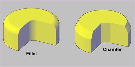
Ever found yourself scratching your head, asking, 'What exactly is the difference between a fillet and a chamfer?' If you're dabbling in mechanical engineering or designing custom mechanical parts, this question might seem all too familiar. You're not alone! The distinction between a fillet and a chamfer, though seemingly straightforward, is actually a crucial element in design. A fillet, known for its rounded edge, contrasts sharply with a chamfer – an object’s edge cut at a distinct angle. But why does this matter, you ask? Let's dive in and find out!
Understanding Fillets
Introduction to Fillets
What is a Fillet?
A fillet, in the realm of design and manufacturing, is a smooth, rounded edge. It's not just any edge; it's a feature that transitions between two faces of a part or material. Picture this: a skateboard ramp, how it smoothly curves at the base. That's what a fillet looks like. In mechanical parts, it's a vital element, distinguishing itself from a chamfer, which is an angled cut.
The characteristics of a fillet include its rounded edge and smooth transition. It's not just for looks; a fillet plays a crucial role in reducing stress concentration in parts. This is especially important in areas prone to fatigue and deformation. Think of it as a buffer, smoothing out high-stress spots in mechanical components.
Types of Fillets: Diverse Variations
Fillets come in various forms, each serving a unique purpose:
1. Miter Fillet: Imagine two boards joined at an angle, with a smooth curve softening their intersection. This is the miter fillet, a staple in woodworking and metal fabrication. It's all about creating a seamless joint.
2. Concave Fillet: The inward curve, like the inside of a bowl. Used extensively in welding and machining, this type of fillet eases the stress on welded joints and machined parts.
3. Convex Fillet: Think of the bulging curve on a car's fender. It's a fillet that protrudes outward, offering both aesthetic appeal and structural integrity. In CNC machining, this type of fillet is used to enhance the strength of a part while maintaining a sleek look.
Each fillet type has its place. In design engineering, choosing the right fillet—be it concave, convex, or miter—can make a world of difference in the functionality and appearance of a part. For instance, in additive 3D printing processes, using the correct fillet can mean fewer print errors and a more robust final product.
Fillets are more than mere design elements. They're integral components in the design and manufacturing world, balancing aesthetics with functionality. Whether it's a Fillet AutoCAD command creating a perfect curve in a digital model or a CNC machining tool smoothly carving out a part, fillets are everywhere, shaping the world of design and manufacturing.
The Role of Fillets in Design and Engineering
Stress Reduction and Structural Benefits
Fillets are not just design elements; they are engineering solutions. Their primary role? Reducing stress concentration. This is a game-changer in mechanical parts. Why? Because stress concentration is a leading cause of material failure. Think of a fillet as a buffer zone. It spreads out stress over a larger area, reducing the risk of cracks and breakage.
Now, let's talk about structural integrity. Fillets add strength. How? By eliminating sharp edges where stress can accumulate, they make parts more durable. It's a simple concept with a big impact. In CNC machining and high-volume production, this translates to longer-lasting, more reliable components.
Aesthetic Contributions of Fillets
Moving beyond functionality, fillets are a touch of class in design. They bring a smooth, refined look to products. This is especially true in consumer goods, where appearance matters as much as performance. A well-placed fillet can transform a basic object into a sleek, modern masterpiece. It's about blending aesthetics with practicality.
In design engineering, fillets are used to soften edges and add visual appeal. They're a designer's tool for creating elegant, flowing lines. It's not just about making things look good; it's about crafting products that feel good in the hand. That's the power of a well-designed fillet.
Fillets in AutoCAD: Usage and Techniques
In the digital world, fillets reign supreme. AutoCAD and similar CAD software use fillet commands to create precise, uniform curves. It's a process that demands both skill and understanding. Using Fillet AutoCAD commands, designers can adjust fillet radii and edges to meet specific requirements.
But it's not just about clicking a button. It's about knowing where and how to apply fillets for maximum effect. In CNC cutting tools and additive 3D printing processes, this knowledge is critical. The right fillet can mean the difference between a good design and a great one. It's about precision, understanding, and a touch of artistic flair.
Applications of Fillets in Various Domains
Fillets are integral to manufacturing, serving not just as a design element, but as a functional necessity. Their role in enhancing product quality, along with their cost-effectiveness, makes them an indispensable tool in modern manufacturing processes. Whether it's a 45° chamfer dimension in a mechanical component or a smooth fillet in a high-end consumer product, these subtle design features make a significant impact in the world of design and engineering.
Fillets Across Industries: Versatile Applications
Fillets are not confined to a single industry; their application spans across various domains. Let's look at a few:
● Aerospace and Automotive: In these high-stress environments, fillets are crucial. They help in managing stress concentrations around corners and joints, ensuring safety and durability.
● Consumer Electronics: Sleek and modern gadgets often employ fillets for both aesthetics and ergonomic comfort. Think of the smooth edges of a smartphone.
● Architecture and Construction: Fillets are used in structures to provide smooth transitions, enhancing both the visual appeal and structural integrity of buildings.
● Medical Devices: Precision is key. Fillets in medical devices reduce sharp edges, which is essential for patient safety and comfort.
Each industry utilizes fillets to address specific needs, be it reducing mechanical stress, improving safety, or enhancing the aesthetic appearance of products.
Fillets in Manufacturing and CNC Machining
In the world of manufacturing, especially CNC machining, fillets assume a role of paramount importance. Here's why:
● Reducing Wear on Tools: Fillets can extend the life of CNC cutting tools. Sharp corners can lead to increased wear and tear, but a smooth fillet eases this stress.
● Enhancing Product Quality: Fillets contribute to the overall quality of machined parts. They help in avoiding stress risers which can lead to part failure under load.
● Cost-Effective Manufacturing: Incorporating fillets can reduce manufacturing costs. They simplify the machining process, reducing the time and effort required to produce complex shapes.
● Precision in Additive Manufacturing: In processes like additive 3D printing, fillets are crucial for achieving precise and smooth contours.
Benefits and Challenges in Fillet Implementation
Advantages of Using Fillets
The inclusion of fillets in design brings a multitude of benefits. Here's a breakdown:
● Reduced Stress Concentration: This is perhaps the most significant advantage. Fillets distribute stress over a larger area, reducing the likelihood of part failure. In mechanical engineering, this aspect is crucial, especially in high-load-bearing components.
● Aesthetic Enhancements: Fillets add a sleek, finished look to products. In consumer goods, this subtle touch can make a product stand out. It's about blending functionality with visual appeal.
● Increased Safety: Smooth edges are safer to handle. This is particularly important in consumer and industrial products where sharp edges can pose risks.
● Ease in Manufacturing: In processes like CNC machining, fillets simplify the manufacturing process. They help in avoiding sharp cuts, making the machining process smoother and more efficient.
Overcoming Challenges in Fillet Implementation
While fillets offer many benefits, their implementation does come with challenges:
● Design Complexity: Integrating fillets requires careful planning in the design phase. It's not just about adding a curve; it's about understanding how that curve affects the entire part.
● Manufacturing Costs: In some cases, adding fillets can increase manufacturing costs, especially if they require complex machining processes or additive 3D printing techniques.
● Material Considerations: The effectiveness of a fillet also depends on the material used. Different materials react differently to stress, and this needs to be considered when designing fillets.
● Balancing Aesthetics and Functionality: It's essential to strike the right balance. Overemphasizing aesthetics can compromise the part's functionality, and vice versa.
Exploring Chamfers
Introduction to Chamfers
Chamfer: Definition and Fundamentals
A chamfer is a pivotal element in both design and manufacturing. Picture a wooden table with its sharp edges cut off at a slant. That slant is what we call a chamfer. It's a transitional edge between two faces of an object - not rounded like a fillet, but cut at an angle, typically 45 degrees. This angled cut creates the chamfered edge, a feature that's both functional and aesthetic.
Chamfers serve a dual purpose:
1. Reducing Sharp Edges: In manufacturing, sharp edges can be a hazard. Chamfers remove these sharp edges, making parts safer to handle. It's a simple yet effective way to enhance safety in both the product and the manufacturing process.
2. Ease of Assembly: Chamfers are particularly useful in aiding the assembly of parts. Think of inserting a square peg into a square hole. A chamfered edge on the peg makes this process smoother, aligning the parts efficiently. This is especially relevant in industries that rely on precision assembly, like mechanical engineering and CNC machining.
3. Aesthetic Appeal: Chamfers can also add a sleek, finished look to products. In design engineering, chamfers are employed to provide a modern and refined appearance to items ranging from everyday gadgets to industrial machinery.
4. Stress Distribution: While fillets are known for reducing stress concentration, chamfers also contribute to distributing stress, especially in parts subject to high-volume production.
Incorporating chamfers into design requires careful consideration of the angle and dimensions. The 45° chamfer dimension is a common choice due to its balanced blend of functionality and aesthetics. Tools like Chamfer AutoCAD command in CAD software simplify the process of adding precise chamfers to digital models, streamlining the transition from design to manufacturing.
Chamfers in Detail: Characteristics and Techniques
Chamfer Characteristics: Types and Features
Chamfers come in various forms and functionalities. Let's delve into their types and features:
● Types of Chamfers: The most common type is the 45° chamfer dimension, ideal for its balance between aesthetics and functionality. However, chamfers can vary significantly in angle and size, depending on their application. Sloped edges are another type, used for both their visual appeal and practicality in fitting parts together.
● Different Chamfer Angles: The angle of a chamfer plays a crucial role in its application. For instance, a steeper angle might be used in parts requiring easier assembly, while a shallower angle could be more about the look and feel of the product. Machined parts often use specific angles to ensure precision and fit.
Chamfering Techniques: From AutoCAD to CNC Machining
Chamfering is a technique refined over time, from manual methods to advanced technological processes.
● AutoCAD Chamfering: In digital design, Chamfer AutoCAD commands are used to create precise chamfered edges. This tool allows designers to specify the dimensions and angles of the chamfer, ensuring accuracy in the design phase. It's about more than just aesthetics; it's about creating a design that's manufacturable.
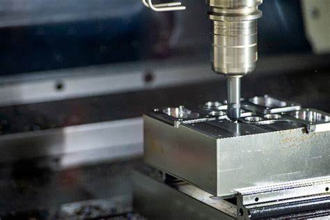
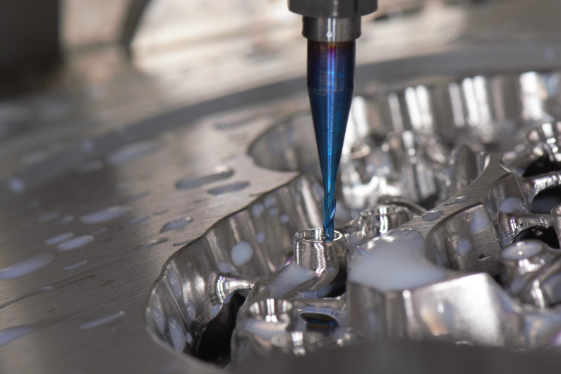
● CNC Machining Chamfering: In the world of CNC machining, chamfering is about precision and efficiency. Using CNC cutting tools, manufacturers can create chamfers with exact angles and depths. This process not only improves the appearance decoration of a part but also enhances its functionality by reducing sharp edges and easing assembly.
● Practical Tips for Chamfer Implementation: When designing chamfers, consider the end use of the part. A part subject to stress concentrations may require a different chamfer compared to one that's more about aesthetic appeal. Additionally, the choice of material can affect the chamfer's effectiveness, especially in manufacturing costs and machining processes.
Chamfers are more than just angled cuts; they are essential components in design and manufacturing that enhance both the functionality and appearance of parts. Understanding the types of chamfers and mastering the techniques to create them, from AutoCAD to CNC machining, is crucial for any designer or manufacturer in today's industry.
Practical Applications and Benefits of Chamfers
Chamfers in Various Industries
Chamfers are not just limited to a specific sector; they're widespread across multiple industries. Let's explore a few:
● Aerospace and Automotive: In these sectors, chamfers play a critical role in aerodynamics and safety. For instance, chamfered edges on airplane wings or car body panels reduce wind resistance and enhance safety.
● Consumer Electronics: Think of the sleek edges of your smartphone or laptop. These are often chamfered for both comfort and style.
● Furniture Manufacturing: Here, chamfers are used not just for their aesthetic appeal but also to prevent injuries from sharp corners.
● Machinery and Equipment: In heavy machinery, chamfers help in easing the assembly of large parts and contribute to the overall durability of the machinery.
In each of these applications, chamfers serve a specific purpose – from enhancing safety to improving usability and appearance.
Advantages of Implementing Chamfers
The benefits of using chamfers in designs are numerous:
1. Easier Assembly: Chamfers can significantly simplify the assembly process. They guide parts into place, especially in complex machinery, making the assembly process smoother and more efficient.
2. Aesthetic Enhancement: A chamfer can transform a basic product into a sleek, modern-looking item. It's a simple touch that can significantly elevate the visual appeal of a design.
3. Improved Safety: By removing sharp edges, chamfers make products safer to handle, reducing the risk of cuts and injuries.
4. Stress Distribution: Similar to fillets, chamfers help in distributing stress along the edges of a part, which can be crucial in high-stress applications like CNC machining and additive 3D printing processes.
5. Cost-Effectiveness: Implementing chamfers can be more cost-effective in certain manufacturing processes. They can reduce the need for additional finishing processes, thus saving time and money.
Overcoming Challenges in Chamfer Implementation
Addressing Challenges and Limitations
While chamfers are beneficial, they come with their own set of challenges and limitations. Here's a look at some potential downsides:
1. Precision in Measurement and Execution: Chamfers require precise measurements and execution. A slight deviation in the 45° chamfer dimension can lead to parts not fitting correctly, especially in high-volume production.
2. Material Limitations: Not all materials are conducive to chamfering. Harder materials can pose a challenge in achieving a smooth, consistent chamfer.
3. Design Restrictions: In some designs, particularly those with space constraints, implementing a chamfer may not be feasible. This is particularly true in compact mechanical parts where every millimeter counts.
4. Aesthetic Consistency: Achieving a uniform look across different chamfers can be challenging, especially when working with manual processes or less advanced machinery.
Cost Implications and Manufacturing Considerations
Implementing chamfers also has cost and manufacturing implications:
1. Increased Manufacturing Time and Cost: Chamfering can add additional steps in the manufacturing process, potentially increasing both time and cost. This is a crucial consideration in CNC machining where efficiency is key.
2. Tool Wear and Maintenance: Chamfering, especially on harder materials, can lead to increased wear on CNC cutting tools. This necessitates more frequent maintenance and potential tool replacement.
3. Complexity in Automated Processes: In automated manufacturing processes like additive 3D printing, adding chamfers can complicate the programming and execution, potentially impacting the overall manufacturing efficiency.
4. Material Wastage: Chamfering can lead to increased material wastage, which can be a significant factor in cost-sensitive projects or in industries where material conservation is a priority.
Comparative Analysis of Fillets and Chamfers
| Differences between Fillet and Chamfer |
| Fillet | Chamfer |
| Safety | Fillet makes the material handling safer. | The sharp edges of chamfer can cause injury. |
| Use | Fillet can avoid sharp edges from hurting people. Internal features often use fillet. | Holes use chamfers for lead-ins. Chamfer is often used for external features. |
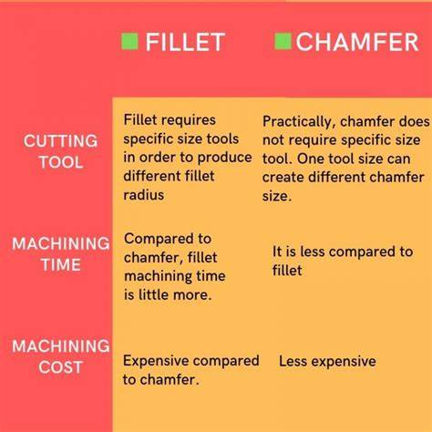
| Cost | If it is milling, relatively speaking, the cost of fillet is higher than that of chamfer. | The cost of chamfer is slightly cheaper when the part is cut by hand. |
| Machining Time | Curved edges are not very easy to make. Unless a ball end mill is used for machining complex shapes, it is more time-consuming than chamfer. | Chamfer takes less time to process than fillet. |
| Cutting Tools | Different cutting tools are required to machine fillets of different radius. | Chamfers of diffrent sizes can be machined with one cutting tool. |
| Coating | Fillet is preferred when coating is required. | There are still sharp edges at the chamfer, and the coating is easy to peel off. |
| Stress Concentration | Fillet shares stress over a larger radius, preventing deformation of the part. | Stress is concentrated on a part, which can easily cause deformation of the material. |
Geometric and Functional Differences
Geometric Differences: Shapes and Structures
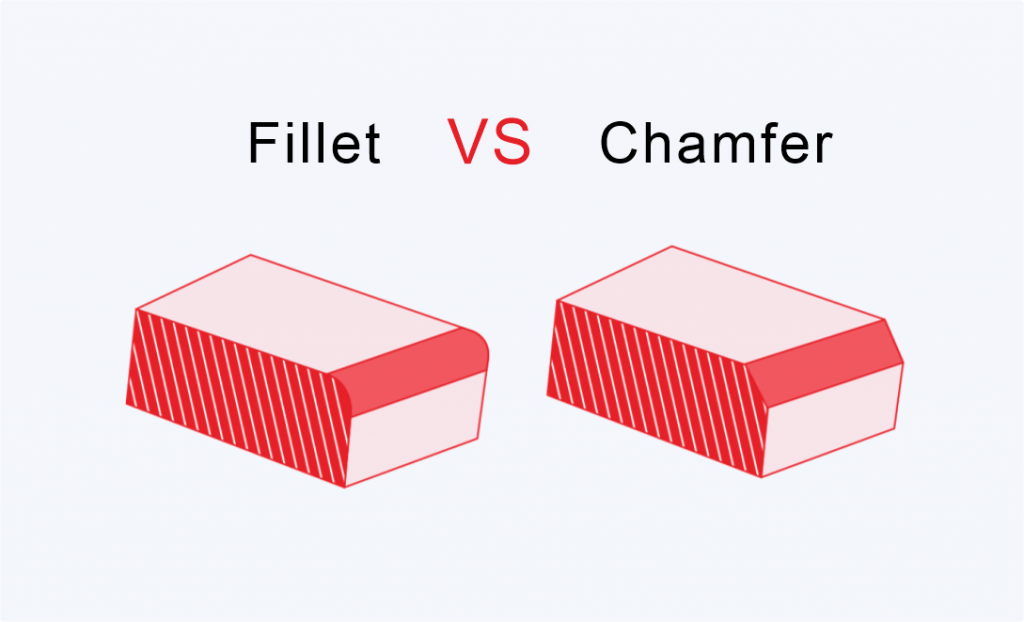
When we delve into the geometric differences between fillets and chamfers, we're talking about more than just aesthetics. Fillets, with their rounded edges, present a smoothly curved transition between two surfaces. This could be where an interior corner meets or along the edges of a mechanical part. In contrast, chamfers typically feature a 45° angle, creating a sloped or angled edge. This difference is not just visible but also impactful in terms of dimension surface and angular dimension.
The implications of these geometric distinctions are significant in design engineering. For instance, a rounded corner of a fillet can distribute stress more evenly across the surface, reducing the likelihood of deformation under mechanical stress. Chamfers, on the other hand, with their angled approach, are often used for facilitating assembling processes, especially when parts need to align precisely, such as in CNC machining.
Functional Differences Between Fillet and Chamfer
Moving to the functional aspects, fillets and chamfers serve distinct purposes in various applications. A fillet is often employed in areas where stress concentration is a concern, like in load-bearing parts. Its rounded nature helps in evenly distributing stress, thereby enhancing the durability of the part. Fillets are a common sight in both subtractive and additive 3D printing processes, where precision and stress reduction are paramount.
Chamfers, conversely, are more about precision and ease of assembly. Their angular dimension makes them ideal for guiding parts into place, often seen in high-volume production where speed and efficiency are key. The chamfered edge also plays a vital role in reducing burrs and sharp corners that can be problematic in both manufacturing and final assembly, enhancing both safety and product quality.
Moreover, when it comes to manufacturing costs and economy, chamfers often require less specialized tooling compared to fillets. Using a standard end mill tool can create a chamfer, while fillets might necessitate more specialty tools or complex machining paths in CNC cutting tools. This difference can influence the decision-making process in design engineering, balancing between cost-effectiveness and the specific requirements of the part.
Stress Concentration and Part Safety
Stress Concentration: Fillet vs. Chamfer
In the realm of design engineering, understanding how fillets and chamfers influence stress concentration in parts is crucial. This aspect significantly impacts the safety and durability of designs, especially in mechanical engineering applications.
Fillet edges, with their rounded profile, are known for their ability to distribute stress across a larger area. This reduction in stress concentration is particularly beneficial in load-bearing parts or where there is a high risk of fatigue or deformation. For instance, in the additive 3D printing process or CNC machining, applying a fillet radii at critical junctions can enhance the mechanical part's longevity and resilience.
In contrast, chamfers, typically featuring a 45° chamfer dimension, offer a different approach to managing stress. While they may not distribute stress as evenly as fillets, chamfers do reduce the occurrence of sharp corners - a common initiation point for cracks and stress concentrations. For machined parts where assembly and disassembly are frequent, chamfers facilitate smoother transitions, reducing the likelihood of part damage.
From a safety perspective, both fillets and chamfers play a pivotal role. In industries like aerospace or automotive, where precision and durability are paramount, the choice between a fillet and chamfer could hinge on the part's exposure to repetitive stress and the necessity for smooth liquid flow or aerodynamics. For example, a rounded edge of a fillet might be preferred in a high-stress part to prevent fatigue failure, while a chamfer might be selected for parts requiring efficient assembly and alignment.
It's also worth noting that in high-volume production, the choice between fillet and chamfer can affect manufacturing costs and time. Fillets might require more complex CNC cutting tools or specialty tools in milling, potentially increasing production time. Chamfers, often easier to create with a standard end mill tool, can be more cost-effective and quicker to produce.
Manufacturing and Economic Considerations
Manufacturing Considerations
In the world of manufacturing, the decision to use a fillet or chamfer can significantly impact both the process and the outcome. Let's break it down:
● Creating Fillets and Chamfers: The creation of fillets often involves more complex CNC cutting tools and techniques. When using Fillet AutoCAD commands, for instance, the tool path must accommodate the rounded edge or fillet radii, requiring advanced machining precision. In contrast, chamfers typically need simpler, straight cuts, easily achieved with a standard end mill tool. This difference can be even more pronounced in additive 3D printing processes, where achieving a smooth fillet may require additional meshing quality control.
● Time and Cost Impact: Time is money, especially in high-volume production. The complex nature of producing fillets often translates into longer manufacturing times and higher costs due to the need for specialized machining or processing methods. Chamfers, with their straightforward 45° chamfer dimension, can be quicker to produce and more cost-effective, especially in bulk manufacturing scenarios.
Economic Aspects: Cost-Effectiveness in Production
Delving into the economics of fillets and chamfers, several factors come into play:
● Cost Implications: Using fillets might increase manufacturing costs due to the need for specialty tools or more complex machining paths in CNC operations. In contrast, chamfers often require less intricate tooling and are generally quicker to produce, potentially leading to cost savings in both materials and labor.
● Scenarios of Cost-Effectiveness: The choice between fillets and chamfers can vary depending on the specific application. For instance, in design engineering where stress reduction and aesthetic appeal are crucial, the extra cost of a fillet might be justified. Conversely, in applications where assembly efficiency and manufacturing speed are priorities, such as in assembly lines or mass-produced parts, the simplicity of chamfers could prove more economical.
Practical Decision-Making in Design
Decision Criteria: When to Use Fillet vs. Chamfer
Choosing between a fillet and a chamfer in design is not just about preference. It's about understanding their functionality and application. Here are some guidelines:
Design Scenarios:
● Use a fillet when dealing with load-bearing parts where stress concentration is a concern. Fillets, with their rounded edges, distribute stress more evenly.
● Opt for a chamfer in parts where assembly efficiency is critical. The angled edges of chamfers aid in easier alignment and assembly of parts.
Case Studies:
● In a recent CNC machining project, a 45° chamfer was used to reduce assembly time, proving effective in high-volume production.
● Another case in additive 3D printing showcased how fillet radii enhanced the durability of a part by reducing stress concentrations at sharp corners.
Design Considerations: Safety, Craftsmanship, and Aesthetic
The choice between fillets and chamfers goes beyond mere functionality. It involves considering safety, craftsmanship, and aesthetics:
Safety:
● Fillet edges are preferred in parts that require smoother surfaces to prevent injuries from sharp corners.
● Chamfers are useful in machined parts where burr reduction is crucial for safe handling and operation.
Craftsmanship and Aesthetics:
● Fillet AutoCAD commands are often used for interior and exterior design elements to give a smooth appearance, enhancing the aesthetic appeal.
● Chamfers, with their clean angular dimensions, provide a sleek and modern look, often used in designing consumer electronics and furniture.
In making these decisions, the designer must balance cost, efficiency, and aesthetic requirements. The use of CNC cutting tools and specialty tools can impact the manufacturing costs and feasibility of the chosen feature. Ultimately, the key is to align the design choice with the specific functions and requirements of the part, ensuring safety and efficiency without compromising on quality and appearance.
Consolution
In exploring the intricate world of fillets and chamfers, we've delved deep into their definitions, types, and roles in both design and engineering. Fillets, known for their rounded edges, not only enhance structural integrity by reducing stress concentration but also contribute significantly to the aesthetics of product design. Their versatile applications across various industries, from AutoCAD design to CNC machining, highlight their pivotal role in manufacturing.
Similarly, chamfers, with their distinct angled edges and types, offer both functional and aesthetic benefits. Their ease in assembly and application in diverse industries underscores their practicality. Yet, the choice between a fillet and chamfer isn't straightforward—it's influenced by factors like geometric differences, safety considerations, and manufacturing costs.
This comparative analysis sheds light on how these two features, each with unique characteristics and applications, influence design decisions. Whether it's choosing a fillet for its stress-distributing properties or a chamfer for its ease of assembly, understanding their distinct roles and impacts is key for any designer or engineer. Balancing safety, craftsmanship, and economic factors is crucial in making the right choice for your specific design scenario.
FAQs
Q: What Are the Common Mistakes in Designing Fillets and Chamfers?
A: One common mistake in designing fillets and chamfers is not considering how they affect the part's strength and material flow during manufacturing, which can lead to stress concentrations and part weakness. Another mistake is specifying fillets and chamfers that are too small or large for the capabilities of the manufacturing process, resulting in poor fit or finish. Designers also often overlook the impact of fillets and chamfers on the ease of assembly, potentially leading to assembly issues or increased manufacturing costs due to additional machining requirements.
Q: How to Choose the Right Fillet or Chamfer for Different Materials?
A: The choice of the right fillet or chamfer for different materials depends on the material properties and the intended application of the part. For brittle materials, larger fillets may be necessary to reduce stress concentrations, while ductile materials may allow for smaller fillets. The manufacturing process also plays a critical role; for example, materials that are difficult to machine may require simpler chamfer geometries to reduce tool wear. Additionally, the function of the part should guide the decision, as areas subject to higher stress or wear may benefit from specific fillet or chamfer dimensions to enhance durability.
Q: What are the key differences between a fillet and a chamfer in CNC machining?
A: In CNC machining, a fillet refers to a rounded interior or exterior corner, while a chamfer is a beveled edge at a specific angle, typically 45 degrees, connecting two surfaces. Fillets are often used to reduce stress concentrations and improve flow in molded parts, making them preferable in high-stress applications. Chamfers, on the other hand, are easier and faster to machine than fillets and are commonly used to facilitate assembly, by allowing clearance for screws or to remove sharp edges for safety.
Q: How do fillets and chamfers contribute to the durability of machined parts?
A: Fillets and chamfers contribute to the durability of machined parts by reducing sharp corners that can cause stress concentrations, which are potential points of failure under cyclic loads or impact. By smoothing the transition between surfaces, fillets can distribute stress more evenly across the part, enhancing its resistance to fatigue and cracking. Chamfers can also protect against edge chipping and make parts easier to handle, further contributing to their longevity.
Q: Can the choice of fillet or chamfer affect the manufacturing cost?
A: Yes, the choice of fillet or chamfer can significantly affect the manufacturing cost. Fillets typically require more complex tool paths and may involve slower machining speeds or multiple passes, increasing machining time and cost. Chamfers are generally simpler to machine and can be done quickly in one pass, making them more cost-effective. Additionally, the size and complexity of the fillet or chamfer can affect the type of tools required and the level of wear they experience, further influencing the overall cost.
Q: Can Fillets and Chamfers Be Automated in Modern CAD Software?
A: Modern CAD (Computer-Aided Design) software can indeed automate the creation of fillets and chamfers, significantly streamlining the design process. These software packages often include features that allow designers to apply fillets and chamfers to edges with just a few clicks, and to define parameters such as radius and angle, which the software then uniformly applies to the selected edges. This automation not only saves time but also ensures consistency across the design, which is crucial for maintaining part quality and performance.


