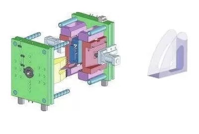
Have you ever wondered how complex plastic parts are made with precision? Injection molding sliders are the key. These essential components help create intricate features in molded products, ensuring smooth and efficient production. In this post, you'll learn why sliders are crucial in the injection molding process and how they make complex parts possible.
What is an Injection Molding Slider?
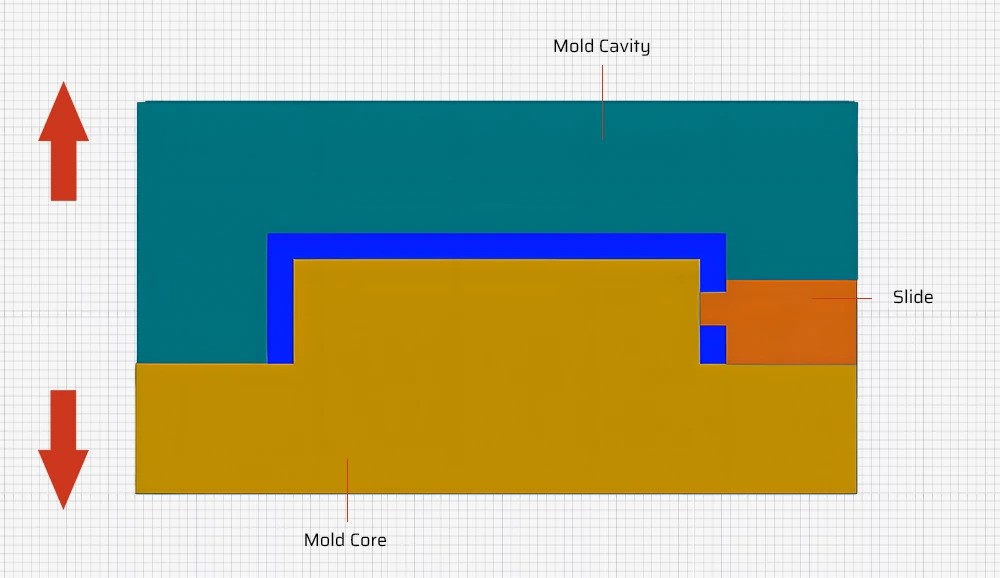
An injection molding slider is a movable component within the mold. It slides in a direction perpendicular to or at an angle to the mold opening direction. This allows the creation of undercuts, holes, and grooves on the molded part.
The basic components of a slider system include:
Why Are Sliders Used in Injection Molding?
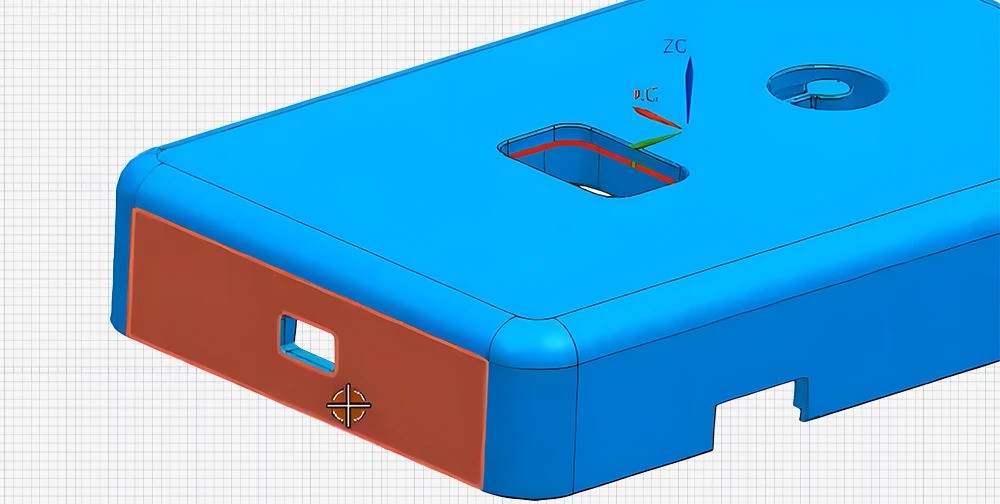
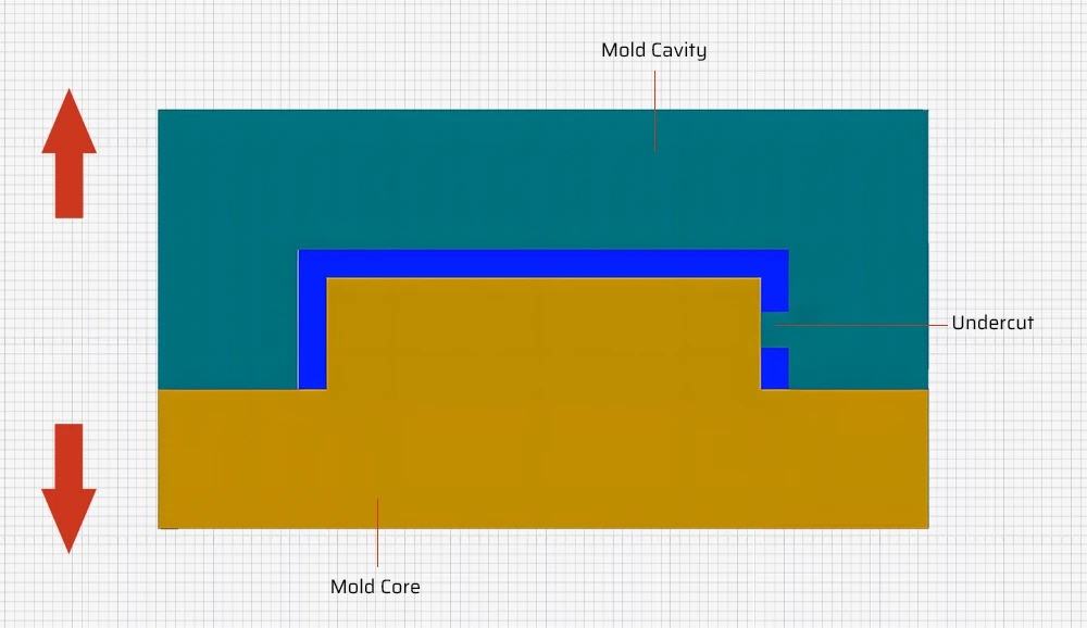
Sliders are crucial when the product has a structure that prevents proper demolding without their use. They are necessary for parts with undercuts, holes, or grooves that can't be directly formed in the mold cavity.
Here's how sliders facilitate smooth demolding:
During the mold opening process, the angled guide pin drives the slider.
The slider moves laterally, releasing the undercut or complex feature.
This allows the molded part to be ejected without damage.
Without sliders, it would be impossible to create many complex plastic parts in a single molding process. They transform the vertical mold opening motion into a horizontal sliding action, enabling the creation of intricate designs.
The slider material must have appropriate hardness and wear resistance to withstand the friction of movement. The hardness of the cavity or core part of the slider should match the rest of the mold.
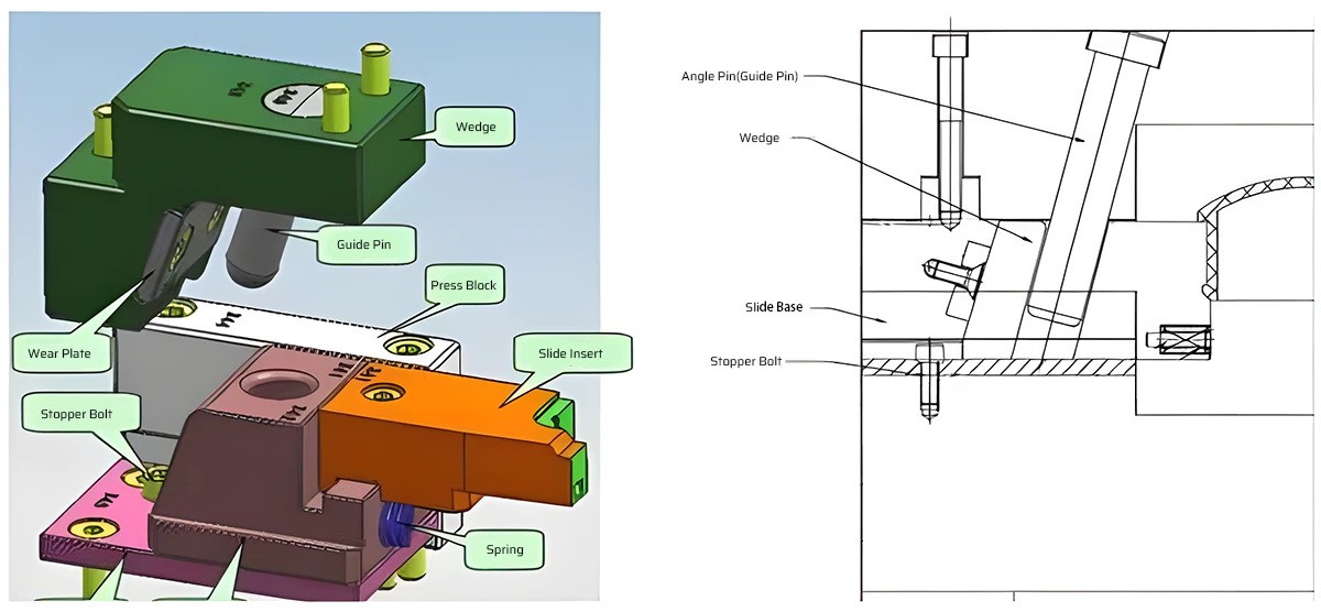
Components of the Slide System
Injection mold sliders consist of several key components. Each part plays a crucial role in ensuring smooth operation and quality molded parts. Let's dive into these components:
Guide Pin (Angle Pin or Horn Pin)
The guide pin, also known as the angle pin or horn pin, is the most common type of slide action. It serves two main functions:
Locating the core and side of the mold cavity
Supporting the weight of the mold
The guide pin should be positioned between 15 and 25 mm above the product. It facilitates easy movement within the mold system.
Slide Body
The slide body is the heart of the slider mechanism. It houses all the components necessary for the sliding action. The slide body provides structural support and ensures coordinated movement.
Wear Plate
Wear plates are designed to reduce friction and wear between moving parts. They help extend the lifespan of the slider components. These plates ensure smooth operation over many molding cycles.
Press Block
The press block exerts pressure and force for proper slider functioning. It supports and guides the upper half of the slider. The press block maintains the distance between the slide and core.
Wedge
The wedge compresses the slider, preventing it from retracting during injection. This is crucial due to the high pressures involved in the molding process. The wedge keeps the slider in place.
Stopper Bolt
The stopper bolt controls the stroke of the slider during movement. It's a screw component fixed on the slider. The stopper bolt prevents excessive travel or movement beyond the designated range.
Springs
Springs assist in slide positioning and return. They ensure the slider returns to the correct position after each molding cycle. Springs play a vital role in maintaining consistency.
Types of Guide Pins
Guide pins are essential components of injection mold sliders. They come in various types, each suited for specific applications.
Thin Mold Plates or Clamped Plates
These guide pins are ideal for thin, separable mold plates. They offer several advantages:
Thin mold plates or clamped plates are commonly used in smaller molds. They are a cost-effective solution for simpler part designs.
Guide Pins for 2 or 3 Part Plates with Thick Plates and Large Mold Cavity
When dealing with thicker plates and larger mold cavities, specific guide pin designs are required. These guide pins have a length-to-diameter ratio of 1.5 or higher.
Length-to-diameter ratio is crucial for several reasons:
Ensures proper alignment of the mold plates
Prevents binding or sticking during mold opening and closing
Maintains the structural integrity of the guide pin
However, guide pins with high length-to-diameter ratios may exhibit some drawbacks:
To mitigate these issues, careful design and material selection are essential. Using high-quality materials and optimizing the guide pin geometry can help ensure smooth operation.
| Guide Pin Type | Characteristics | Applications |
| Thin Mold Plates or Clamped Plates | Good stability Matte surface finish | |
| Guide Pins for 2 or 3 Part Plates with Thick Plates and Large Mold Cavity | | Thicker plates Larger mold cavities Complex part designs |
The Role of the Guide Block (Slider)
The guide block, also known as the slider, is a crucial component of the injection mold slider system. It works in tandem with the guide pin to ensure smooth and precise movement.
Complementing the Guide Pin's Function
The guide block complements the function of the guide pin. While the guide pin provides location and support, the guide block facilitates the sliding motion. This partnership is essential for the proper functioning of the slider mechanism.
Exerting Force on the Guide Pin
The guide block exerts a force on the guide pin. This force helps keep the guide pin in place, even under the high pressures of the injection molding process. By maintaining the guide pin's position, the guide block ensures the accuracy and consistency of the slider's movement.
Guiding the Motion of the Guide Pin
The guide block also serves to guide the motion of the guide pin. It provides a smooth and controlled path for the guide pin to follow. This guidance is crucial for maintaining the alignment and precision of the slider mechanism.
The guide block typically features a T-shaped guide slot. This slot design allows for optimal guidance and support of the guide pin. The guide block should be made from hardened steel to withstand the repeated sliding action.
Facilitating Both Vertical and Horizontal Motion
One of the key roles of the guide block is to facilitate both vertical and horizontal motion. During the injection molding process, the slider needs to move in two directions:
Vertical motion: This is the up and down movement of the slider, which is driven by the guide pin.
Horizontal motion: This is the lateral movement of the slider, which allows for the creation of undercuts and complex features.
The guide block's design enables this dual-direction motion. Its interaction with the guide pin and the slider body allows for a seamless transition between vertical and horizontal movement.
| Guide Block Function | Description |
| Complementing Guide Pin | Works in tandem with the guide pin for smooth and precise movement |
| Exerting Force | Helps keep the guide pin in place under high injection molding pressures |
| Guiding Motion | Provides a controlled path for the guide pin to follow, maintaining alignment and precision |
| Facilitating Vertical and Horizontal Motion | Enables the slider to move in both up-down and lateral directions |
Types of Injection Molding Sliders
Injection molding sliders come in different types, each with specific characteristics and use cases. Let's explore two common types: cam pin slides and hydraulic slides.
Cam Pin Slides (Angle Pins)
Cam pin slides, also known as angle pins, are the most common type of slide action. They feature an angled guide pin that withdraws from an angled hole inside the slider body. This metal pin is mounted on the stationary side of the mold and uses an angle block to lock the slide in place.
Advantages of cam pin slides include:
Simplicity and reliability
Automatic return to the proper position when the mold closes
Cost-effectiveness compared to other slide types
However, cam pin slides also have some limitations:
Hydraulic Slides
Hydraulic slides are used when greater control and precision are required. They are particularly beneficial in situations where mechanical slides may exert too much pressure on the guide block, leading to wear and tear.
Hydraulic slides offer several advantages:
Precise control over the timing and sequence of slide movement
Ability to manage high injection pressures without excessive wear
Smooth and consistent slide action
Locking hydraulic cylinders can be used for undercuts on the cavity side of the tool. They provide additional security and precision in these challenging applications.
| Slide Type | Characteristics | Use Cases |
| Cam Pin Slides (Angle Pins) | Angled guide pin Automatic return Cost-effective | |
| Hydraulic Slides | Precise control Handles high pressures Smooth action | |
How Do Injection Molding Sliders Work?
Injection molding sliders play a crucial role in creating complex parts. But how exactly do they function? Let's explore the working principle and step-by-step process of these ingenious components.
Working Principle of Sliders
Sliders don't have circuits or hydraulic cylinders. So, where does their power come from? The answer lies in the angled guide posts.
During the mold opening and closing process, the angled guide posts generate friction with the inner wall of the slider. This friction force drives the entire slider system to move perpendicular to the demolding direction.
The up and down movement of the slide angle pin drives the whole slider system. It's a simple yet effective mechanism that harnesses the mold's motion to create complex features.
Step-by-Step Process
Let's break down the slider operation during an injection molding cycle:
Mold Closing:
The angled guide post engages with the slider.
The slider moves into position, aligning with the mold cavity.
Injection:
Molten plastic fills the mold cavity and the slider.
The wedge compresses the slider, preventing retraction due to injection pressure.
Cooling:
Mold Opening:
The mold opens, and the angled guide post withdraws from the slider.
The slider moves laterally, releasing the undercut or complex feature.
Ejection:
Ejector pins push the molded part out of the mold.
The slider returns to its original position, ready for the next cycle.
Throughout this process, the stopper bolt controls the slider's stroke, and springs assist in positioning and return. It's a well-orchestrated dance that results in perfectly molded parts.
Step-by-Step Guide to Designing an Injection Mold Slide
Designing an injection mold slide requires careful consideration and attention to detail. Follow this step-by-step guide to ensure a successful slide design.
1. Initial Design Considerations
Start by thoroughly reviewing the part design. Identify features that require the use of slides, such as undercuts, threads, or complex shapes. These features will dictate the type and number of slides needed.
2. Material Selection
Choose appropriate materials for the slides. Common options include tool steel, aluminum, and beryllium copper. Ensure the selected material is compatible with the mold material and the specific molding process. Consider factors like hardness, wear resistance, and thermal properties.
3. Determining Slide Type and Number
Based on the identified features, select the appropriate slide type. Determine the number of slides required to effectively create the desired features. Complex parts may require multiple slides working in tandem.
4. Calculating Slide Dimensions
Calculate the dimensions of the slides to ensure proper movement and clearance within the mold cavity. Consider the part design and the selected slide type. The slide should have sufficient space to move without interfering with other mold components. The slider guide should be made with a 0.5mm clearance on one side.
5. Draft Angle Considerations
Incorporate draft angles into the slide design to prevent damage to the part during ejection. Draft angles facilitate the smooth release of the molded part from the slide. Ensure the draft angles are appropriate for the specific material and part geometry.
6. Interlocking Features
Design interlocking features to prevent unwanted movement of the slides during the molding process. These features help maintain the integrity and accuracy of the slides. They also ensure the slides return to their proper position after each molding cycle. Remember to position the stopping block at the end of longer slider pins to avoid deformation.
7. Designing for Manufacturability
Optimize the slide design for ease of manufacturing, assembly, and maintenance. Consider the specific manufacturing processes and equipment available. Streamline the design to minimize complexity and reduce the potential for errors. Aim for a design that is both functional and efficient to manufacture.
| Design Step | Key Considerations |
| Initial Design Considerations | |
| Material Selection | |
| Determining Slide Type and Number | |
| Calculating Slide Dimensions | |
| Draft Angle Considerations | |
| Interlocking Features | |
| Designing for Manufacturability | Optimize for ease of manufacturing, assembly, and maintenance Consider specific manufacturing processes and equipment |
For more information on injection mold components and injection mold design, visit our comprehensive guides.
Common Mistakes to Avoid in Injection Mold Slide Design
Designing injection mold slides can be complex. Avoiding common mistakes is crucial for creating effective and reliable slides. Let's see some pitfalls to watch out for.
Neglecting Draft Angle Considerations
One of the most critical errors is neglecting draft angles. Inadequate draft angles can lead to several issues:
Difficulty ejecting the part from the mold
Damage to the part during ejection
Increased wear on the slide and mold surfaces
To prevent these problems, ensure proper draft angles for both the part and the slide. The specific draft angle required depends on the material and part geometry. As a general rule, aim for a minimum draft angle of 1° to 2°.
Inappropriate Material Selection
Choosing the wrong material for your slides can have serious consequences. Incompatible materials can lead to:
When selecting materials, prioritize durability and compatibility with the mold material and molding process. Common options include tool steel, aluminum, and beryllium copper. Consider factors like hardness, wear resistance, and thermal properties.
Overly Complex Slide Designs
While slides enable the creation of complex features, overly complicated slide designs can be problematic. Drawbacks of excessive complexity include:
Increased manufacturing and maintenance costs
Higher risk of malfunction or failure
Difficulty in assembly and disassembly
To avoid these issues, prioritize simplicity and effectiveness in your slide designs. Focus on creating slides that are functional, reliable, and easy to manufacture. Avoid unnecessary features or intricate geometries that add complexity without significant benefits.
Omitting Interlocking Features
Interlocking features are essential for preventing unwanted movement of the slides during the molding process. Neglecting to include these features can result in:
Misalignment of the slides
Inconsistent part quality
Damage to the mold or slides
Incorporate interlocking features into your slide design to maintain slide integrity and accuracy. These features ensure that the slides remain in their intended position throughout the molding cycle.
| Common Mistake | Consequences | Solutions |
| Neglecting Draft Angles | Difficult ejection Part damage Increased wear | |
| Inappropriate Material Selection | Premature wear Poor sliding performance Reduced part quality | Choose durable and compatible materials Consider hardness, wear resistance, and thermal properties |
| Overly Complex Slide Designs | | |
| Omitting Interlocking Features | | |
For more information on injection molding processes and techniques, check out our guides on injection molding defects and injection mold design. To understand more about the components involved, refer to our article on 10 parts of injection mold.
Injection Molding Slide vs. Lifter
Injection molding slides and lifters are both used to create undercuts and complex features in molded parts. However, they have distinct differences in their meaning, application, and mechanical mechanisms.
Meaning and Application
Lifter:A lifter is a mechanism used to shape barbs or protrusions within the product. It is suitable for creating simple barbs and is commonly used in the following applications:
Electrical processing equipment for copper-based and iron-based powder products
Rubber molding, such as tire molds and "O" seal rubber molds
Plastic products with thermosetting and thermoplastic molding
Slider:A slider is a mold component that can slide in the mold opening direction or at a certain angle to the opening direction. It is used when the product structure makes it impossible to release the molded part without the use of a slider. Sliders are widely used in various fields, including:
CNC machines and machining centers
Automotive and medical equipment
Electronics and automation machinery
Injection molding machines and mold opening systems
Mechanical Mechanism
Lifter:Lifters employ various ejecting mechanisms to shape and release the barbs within the product. These mechanisms include:
Pushing block ejecting mechanism
Molding parts ejecting mechanism
Air pressure ejecting mechanism
Multi-component integrated ejecting mechanism
Slanting slider ejecting mechanism
The specific mechanism used depends on the complexity of the barb and the material being molded.
Slider:Sliders use a core pulling mechanism to release the molded part from the mold. The slider is connected to the molding core and driven by an inclined guide column. During the mold opening process, the slider moves laterally, pulling the core and releasing the undercut or complex feature.
The slider material itself must have appropriate hardness and wear resistance to withstand the friction of the movement. The hardness of the cavity or core part of the slider should match the rest of the mold.
| Feature | Lifter | Slider |
| Meaning | Shapes barbs within the product | Sliding component in mold opening direction |
| Application | Simple barbs, electrical processing equipment, rubber molding | Complex undercuts, CNC machines, automotive, medical equipment |
| Mechanical Mechanism | Pushing block, molding parts, air pressure ejecting | Core pulling mechanism driven by inclined guide column |
| Material Requirements | Depends on the specific application | Appropriate hardness and wear resistance to withstand friction |
Inner Slider Mechanism
When the side slider and slant top mechanism cannot be designed, the inner slider mechanism comes into play. It's a unique solution for creating undercuts and complex features on the inner side of the product.
Design Considerations for Inner Slider Body
The inner slider body is the core component of the inner slider mechanism. Here are some key design considerations:
Driven to the inner side of the product: The inner slider is driven towards the inner side of the product, unlike the common slider mechanism.
Direction of backhoe bit: The direction of the backhoe bit is opposite to the direction of the inclined guide column in the common slider mechanism. This allows for the creation of undercuts on the inner side.
Spring-loaded to prevent backward movement: The inner slider is spring-loaded to prevent it from moving backward without closing the mold. This ensures proper positioning and prevents damage to the mold.
Wear-resistant block for friction and core extraction: A wear-resistant block is used with the inner slider to provide friction and drive the slider core extraction. This block also helps reset the slider.
Multiple Angle Pins and Guide Bars for Wider Sliders
For wider sliders, additional support and guidance are necessary. Here's what you need to consider:
If the slider width exceeds 60 mm, deployment of 2 angle pins should be considered.
For sliders wider than 80 mm, a guide bar needs to be placed under the slider in the middle.
These additional components help distribute the force and ensure smooth operation of the inner slider mechanism.
Lowering Angle Pin Hole Starting Point for Taller Sliders
Taller sliders require a modification to the angle pin hole position. If the slider is too high, the starting point of the angle pin hole needs to be lowered. This adjustment ensures smooth travel of the slider and prevents any interference with other mold components.
| Slider Width | Design Considerations |
| < 60 mm | Single angle pin |
| 60-80 mm | 2 angle pins |
| > 80 mm | 2 angle pins + guide bar under the slider |
| Slider Height | Design Considerations |
| Standard | No modification |
| Too high | Lower the starting point of the angle pin hole |
The inner slider mechanism is a clever solution for creating undercuts and complex features on the inner side of the product. By carefully considering the design of the inner slider body, incorporating multiple angle pins and guide bars for wider sliders, and adjusting the angle pin hole position for taller sliders, you can ensure the smooth operation and effectiveness of the inner slider mechanism.
Handloads in Injection Molding
Handloads offer an alternative to sliders and lifters for low-volume production in injection molding. They are manually placed inserts that create undercuts and complex features in the molded part.
Alternative to Sliders and Lifters for Low-Volume Production
Sliders and lifters are automated mechanisms that release undercuts and complex features in injection molded parts. However, they can be expensive for low-volume production runs. This is where handloads come into play.
Handloads are a cost-effective solution for prototypes and low-volume production. They eliminate the need for expensive automated mechanisms, making them an economical choice for these applications.
Manually Placed Inserts to Create Undercuts and Complex Features
Handloads are manually placed inserts that create undercuts and complex features in the molded part. Before the mold cavity is filled, a worker loads the insert by hand. This hand-loaded piece is ejected with the finished part and removed so it can be reinserted during the next injection molding cycle.
Handloads can create a wide range of features, including:
Undercuts
Threads
Complex geometries
Side holes
Channels and grooves
Economical for Prototypes and Low Volumes
While handloads add labor costs to the injection molding process, they are still economical for prototypes and low-volume production. The cost savings from not requiring expensive automated mechanisms like sliders and lifters offset the added labor costs.
Handloads are particularly suitable for:
Prototyping and testing new designs
Low-volume production runs (typically less than 1,000 parts)
Parts with complex geometries that would be difficult or expensive to create with automated mechanisms
Considerations for Consistent Cycling and Proper Cooling
As an extension of the injection mold, handloads require precise temperatures for molding quality and part-to-part consistency. Here are some key considerations:
Consistent cycling: If a part requires multiple hand-loaded inserts, consistent cycling may be challenging. To maintain proper production cycle times, it's essential to build multiple hand loads and use special fixtures to facilitate the extraction of complex parts.
Proper cooling: Handloads must be designed to support proper cooling between cycles. They should be built from materials that can withstand the temperature fluctuations of the injection molding process. Proper cooling helps ensure the quality and consistency of the molded parts.
Low-pressure mold closing: It's crucial for the molder to use a low-pressure mold close to minimize potential hand load damage. This helps extend the life of the handloads and ensures the quality of the molded parts.
| Handloads | Sliders and Lifters |
| Manually placed inserts | Automated mechanisms |
| Economical for low-volume production | Cost-effective for high-volume production |
| Suitable for prototypes and complex geometries | Ideal for large production runs and simpler geometries |
| Require consistent cycling and proper cooling considerations | Designed for automated, consistent operation |
Conclusion
Understanding injection molding sliders is crucial for creating complex parts with precision. Sliders ensure smooth demolding by addressing undercuts, grooves, and other challenging features. We've covered their definition, components, and why they’re essential in the molding process.
We've delved into the various components of the slide system, the types of guide pins, and the working principle behind sliders. The step-by-step design guide provided a roadmap for creating effective slider systems while avoiding common mistakes.
As an injection molding professional, having a deep understanding of sliders is crucial for creating high-quality, complex parts efficiently. By applying the knowledge gained from this guide, you can optimize your injection molding processes and tackle even the most challenging designs with confidence.


