In the realm of engineering and machining, holes play a crucial role in the design and functionality of various components. Among these, blind holes, also known as non-through holes, are of particular significance. This article aims to provide a comprehensive overview of blind holes, their applications, and best practices in design and manufacturing.
Understanding Blind Holes
In the world of engineering and machining, holes play a crucial role in the design and fabrication of various components. Among the different types of holes, blind holes stand out due to their unique characteristics and wide range of applications. This section aims to provide a comprehensive understanding of blind holes, including their definition, characteristics, materials, tools, and applications in various industries.
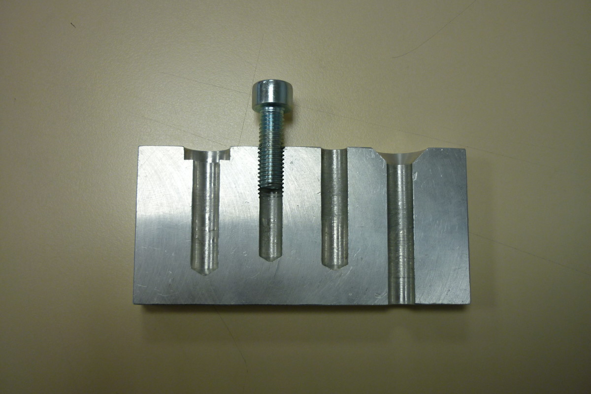
Definition and Characteristics of Blind Holes
A blind hole, also known as a non-through hole, is a type of hole that is drilled, milled, or bored to a specific depth without breaking through to the opposite side of the workpiece. In other words, a blind hole has a bottom, unlike a through-hole, which penetrates the entire thickness of the material.
Key characteristics of blind holes include:
● Partially drilled into the workpiece, with a defined depth
● One open end and one closed end (bottom)
● Can be threaded or unthreaded, depending on the application
● Offers increased structural integrity compared to through-holes
Blind holes differ from through-holes in several aspects:
Characteristic | Blind Hole | Through-Hole |
Depth | Partial | Full |
Ends | One open, one closed | Both open |
Strength | Higher | Lower |
Machining | More complex | Simpler |
Materials and Tools Used in Creating Blind Holes
Blind holes can be created in a wide range of materials, depending on the specific application and required properties. Some common materials suitable for blind holes include:
● Metals: Aluminum, steel, stainless steel, titanium, etc.
● Plastics: Acrylic, nylon, polycarbonate, PEEK, etc.
● Composites: Carbon fiber reinforced polymers (CFRP), glass fiber reinforced polymers (GFRP), etc.
To create blind holes, various tools and machinery are employed, such as:
● Drills: Twist drills, spot drills, core drills, etc.
● CNC machines: CNC mills, CNC lathes, CNC drills, etc.
● Boring tools: Boring bars, boring heads, etc.
● Taps: Bottoming taps, spiral flute taps, roll taps, etc. (for threaded blind holes)
Applications of Blind Holes in Various Industries
Blind holes find extensive applications across various industries due to their unique advantages and versatility. Some examples of industries where blind holes are crucial include:
1. Aerospace:
a. Lightweighting of aircraft components
b. Fastener holes in airframe structures
c. Fuel injection nozzles in jet engines
2. Automotive:
a. Engine block and transmission component design
b. Suspension and brake system parts
c. Threaded holes for fasteners and sensors
3. Electronics:
a. PCB mounting holes for components
b. Heatsink attachment points
c. Enclosure design for electronic devices
Specific parts and assemblies that typically require blind holes are:
● Bolted joints and fastening points
● Bearing housings and bushings
● Fluid and gas flow channels
● Sensor and probe mounting points
● Tooling and fixture design
Types and Functions of Holes in Engineering
Holes are a fundamental aspect of engineering and machining, serving various purposes in the design and functionality of components. This section explores the different types of holes commonly used in engineering, with a focus on counterbored holes, countersunk holes, and spot faces. Additionally, we will discuss the functional benefits of blind holes and their impact on design and aesthetics.
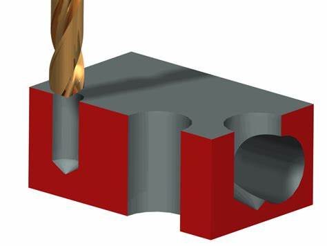
Different Types of Holes and Their Uses
Counterbored Holes
A counterbored hole consists of a larger diameter hole that is partially drilled into a workpiece, followed by a smaller diameter hole that extends through the remaining thickness. The larger diameter portion is called the counterbore, and it allows the head of a fastener to sit flush with or below the surface of the workpiece.
Characteristics of counterbored holes:
● Two-step hole design: counterbore and smaller through-hole
● Flat bottom in the counterbore portion
● Accommodates fasteners with a cylindrical head
Applications of counterbored holes:
● Mounting bolts, screws, or other fasteners flush with the surface
● Providing clearance for the head of a fastener
● Enhancing the appearance of assembled components
Countersunk Holes
A countersunk hole is similar to a counterbored hole but features a conical shape in the larger diameter portion instead of a flat bottom. This conical shape allows fasteners with a flat head to sit flush with the surface of the workpiece, creating a smooth and streamlined appearance.
Characteristics of countersunk holes:
● Two-step hole design: countersink and smaller through-hole
● Conical shape in the countersink portion
● Accommodates fasteners with a flat head
Applications of countersunk holes:
● Providing a flush surface for flat head fasteners
● Reducing drag and improving aerodynamics in aircraft and vehicles
● Enhancing the aesthetics of assembled components
Spot Faces
A spot face is a shallow counterbore that is used to create a flat, smooth surface around a hole. It is typically used to provide a perpendicular mating surface for the head of a fastener or a washer, ensuring proper seating and load distribution.
Characteristics of spot faces:
● Shallow counterbore around a hole
● Creates a flat, perpendicular surface
● Improves fastener seating and load distribution
Applications of spot faces:
● Providing a flat mating surface for fasteners and washers
● Enhancing the accuracy and stability of assembled components
● Improving the appearance of machined surfaces
Functional Benefits of Blind Holes
Blind holes offer several functional benefits in engineering and machining:
1. Increased strength: Blind holes maintain the structural integrity of a component by not penetrating through the entire thickness, reducing stress concentrations.
2. Weight reduction: By eliminating unnecessary material removal, blind holes help reduce the overall weight of components without compromising strength.
3. Improved sealing: Blind holes can be used to create sealed cavities or pockets for retaining lubricants, gases, or fluids.
4. Enhanced thread engagement: Blind holes provide more thread engagement for fasteners compared to through-holes, resulting in stronger and more secure connections.
Impact on Design and Aesthetics
The choice of hole type can significantly impact the design and aesthetics of engineered components:
1. Flush surfaces: Counterbored and countersunk holes allow fasteners to sit flush with the surface, creating a smooth and streamlined appearance.
2. Clean and professional look: Properly designed and machined holes contribute to the overall visual appeal and perceived quality of a component.
3. Improved ergonomics: Flush surfaces and well-placed holes can enhance the ergonomics of a product, making it more comfortable and user-friendly.
4. Consistent branding: The strategic use of hole types can contribute to a consistent and recognizable brand identity across a range of products.
Machining Techniques for Blind Holes
Blind holes play a crucial role in various engineering applications, and their precise machining is essential for ensuring the desired functionality and performance of the final product. This section will delve into the various machining techniques used for creating blind holes, including drilling, boring, tapping, and advanced methods such as gun drilling and trepanning. We will also discuss tooling and equipment considerations, as well as the challenges faced during the machining process and their solutions.
Drilling and Boring Methods
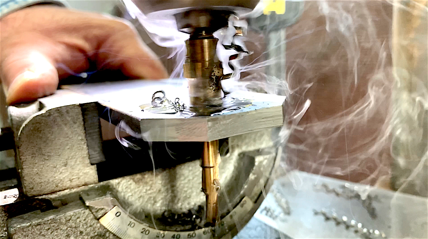
Drilling is the most common method for creating blind holes. The step-by-step process for drilling blind holes involves:
1. Selecting the appropriate drill bit based on the desired hole diameter and material.
2. Setting the depth stop or using a drill bit with a depth marker to ensure the correct hole depth.
3. Securing the workpiece firmly to prevent movement during drilling.
4. Applying cutting fluid to lubricate the drill bit and remove chips.
5. Drilling the hole at the appropriate speed and feed rate, periodically retracting the drill bit to clear chips.
6. Verifying the hole depth and quality using measuring tools.
To maintain accuracy and prevent common drilling errors:
● Use sharp, high-quality drill bits suitable for the material being drilled.
● Ensure proper alignment of the drill bit with the workpiece.
● Apply steady, controlled pressure during drilling.
● Adjust the speed and feed rate according to the material and hole size.
● Regularly clear chips from the hole to prevent drill bit breakage and ensure a clean hole.
Boring is another method used for creating blind holes, particularly when a high degree of precision and surface finish is required. Boring involves using a single-point cutting tool to enlarge a previously drilled hole to the desired size and depth.
Advanced Techniques: Gun Drilling and Trepanning
Gun drilling is an advanced machining technique used for creating deep, precise blind holes with high length-to-diameter ratios. The process involves using a specialized gun drill with a high-pressure coolant system that delivers cutting fluid to the drill tip, effectively removing chips and preventing drill breakage.
Trepanning is another advanced technique for creating large-diameter blind holes. It involves using a special trepanning tool that cuts a circular groove into the workpiece, leaving a solid core that can be removed later. Trepanning is often used when the required hole diameter is too large for conventional drilling methods.
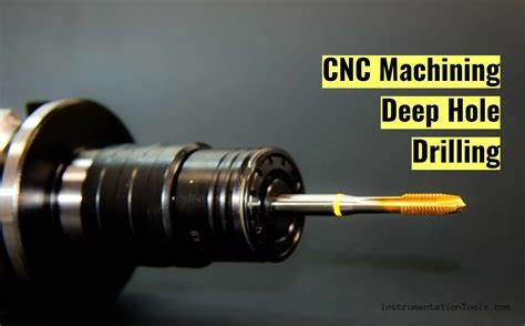
Tooling and Equipment Considerations
Selecting the appropriate tooling and equipment is crucial for the successful machining of blind holes. Some key considerations include:
● Choosing the right drill bit material and coating based on the workpiece material and desired hole quality.
● Using high-quality, rigid machine tools with adequate spindle power and stability.
● Employing suitable workholding devices to ensure proper alignment and prevent workpiece movement.
● Utilizing cutting fluids and coolants to reduce heat generation, improve tool life, and enhance hole quality.
Tapping Techniques for Blind Holes
Tapping is the process of creating internal threads in a previously drilled blind hole. The selection of the correct tap type and size is crucial for achieving the desired thread quality and preventing tap breakage. Some common tap types used for blind holes include:
● Bottoming taps: Designed with a short lead and full threads up to the bottom of the tap, suitable for threading to the bottom of a blind hole.
● Spiral point taps: Featuring a pointed end and spiral flutes that guide chips forward, ideal for blind holes in through-hole applications.
● Forming taps: Used to create threads by displacing material rather than cutting, resulting in stronger threads and less chip formation.
When tapping blind holes, it is essential to:
● Ensure adequate lubrication and chip removal to prevent tap breakage.
● Maintain proper alignment of the tap with the hole axis.
● Apply steady, controlled pressure and reverse the tap periodically to break chips.
● Use a tapping guide or fixture to ensure perpendicularity and prevent tap wobble.
Challenges in Drilling and Tapping
Machining blind holes comes with its own set of challenges, primarily related to chip removal and tool alignment. Common issues faced while working with blind holes include:
● Chip congestion: As the hole depth increases, chip removal becomes more difficult, leading to tool breakage and poor hole quality.
● Tool alignment: Maintaining proper alignment of the drill bit or tap with the hole axis is crucial for preventing tool deflection and ensuring hole straightness.
● Coolant delivery: Ensuring adequate coolant reaches the cutting edge can be challenging, particularly in deep blind holes.
To overcome these challenges, machinists can employ various solutions and preventative measures, such as:
● Using high-pressure coolant systems or through-tool coolant delivery to flush out chips effectively.
● Employing guide bushings, pilot holes, or specialized fixtures to maintain tool alignment.
● Periodically retracting the tool to break and remove chips.
● Selecting tools with chip-breaking geometries or coatings that facilitate chip evacuation.
● Adjusting the cutting parameters, such as speed and feed rate, to optimize chip formation and removal.
Design Considerations for Blind Holes
Designing parts with blind holes requires careful consideration to ensure the desired functionality, manufacturability, and overall quality of the final product. This section will explore the key design aspects engineers must take into account when incorporating blind holes into their components, including hole geometry, material selection, tolerances, and the interaction with other features.
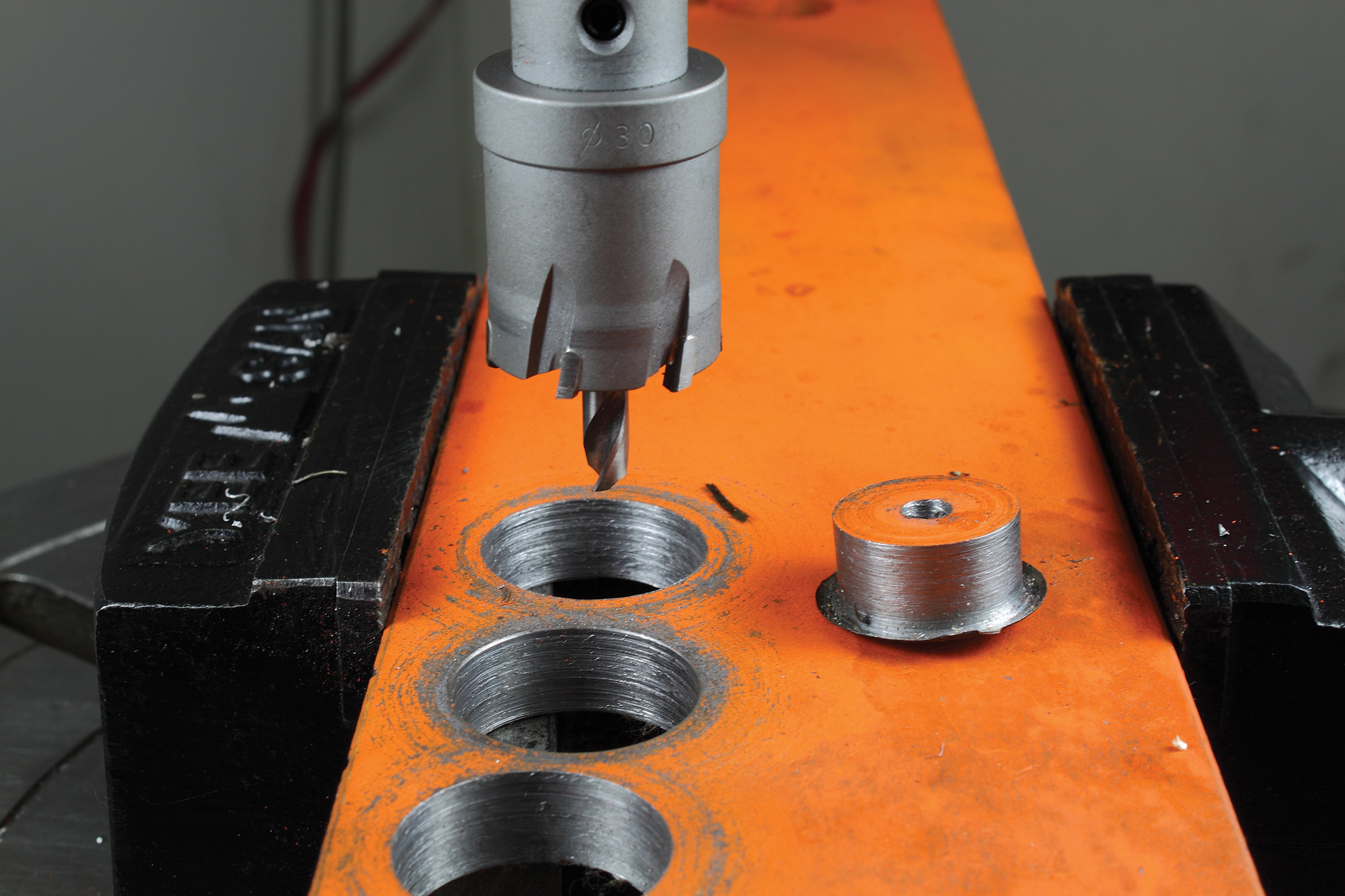
Hole Geometry: Depth and Diameter
One of the primary design considerations for blind holes is determining the appropriate hole geometry, specifically the depth and diameter. The depth of a blind hole is typically dictated by the functional requirements of the component, such as the desired thread engagement length for a tapped hole or the necessary clearance for a mating part.
When selecting the hole diameter, designers must consider:
● The size of the mating component or fastener
● The required strength and load-bearing capacity
● The available space within the component
● The machining capabilities and tooling limitations
It is crucial to strike a balance between the hole depth and diameter to ensure the structural integrity of the component while meeting the functional demands.
Material Selection and Properties
The choice of material plays a significant role in the design and machinability of blind holes. Different materials exhibit varying properties that influence the drilling and tapping processes, such as hardness, ductility, and chip formation.
Common materials used in components with blind holes include:
● Metals: Aluminum, steel, stainless steel, titanium, brass
● Plastics: Nylon, acetal, polycarbonate, PEEK
● Composites: GFRP, CFRP, FRP
When selecting a material, designers must consider:
● The required strength and durability of the component
● The compatibility with the mating components or fasteners
● The machinability and ease of creating blind holes
● The cost and availability of the material
Tolerances and Surface Finish Requirements
Specifying appropriate tolerances and surface finish requirements is essential for ensuring the proper fit, function, and quality of blind holes. Tolerances dictate the acceptable variation in hole dimensions, such as depth, diameter, and positional accuracy.
Factors to consider when specifying tolerances for blind holes include:
● The functional requirements and mating components
● The manufacturing process capabilities and limitations
● The inspection and measurement methods available
Surface finish requirements, typically expressed in terms of roughness average (Ra) or maximum roughness depth (Rmax), influence the performance and appearance of blind holes. A smooth surface finish is often desirable for:
● Improving the fatigue strength and durability of the component
● Reducing friction and wear in mating surfaces
● Enhancing the aesthetic appearance of visible surfaces
Interaction with Other Features and Components
Blind holes rarely exist in isolation; they often interact with other features and components within an assembly. Designers must consider how the placement, orientation, and design of blind holes affect the overall functionality and manufacturability of the product.
Key considerations include:
● Ensuring adequate clearance and accessibility for drilling and tapping tools
● Avoiding interference with other features, such as adjacent holes or edges
● Optimizing the load distribution and stress concentration around the blind hole
● Facilitating the assembly process and minimizing the risk of misalignment
Design for Manufacturability and Assembly
Designing blind holes with manufacturability and assembly in mind is crucial for streamlining production processes and reducing costs. Designers should collaborate with manufacturing engineers and machinists to ensure that the designed blind holes can be efficiently and consistently produced.
Some best practices for designing blind holes for manufacturability and assembly include:
● Standardizing hole sizes and tolerances whenever possible
● Minimizing the depth-to-diameter ratio to facilitate drilling and tapping
● Providing adequate room for chip evacuation and coolant flow
● Incorporating chamfers or countersinks to aid in tool alignment and entry
● Considering the use of thread-forming screws or inserts for easier assembly
By carefully considering these design aspects and working closely with manufacturing teams, engineers can create components with blind holes that meet the desired functional requirements while optimizing manufacturability, quality, and cost-effectiveness.
Advantages and Limitations of Blind Holes
Blind holes are essential features in various engineering applications, offering unique benefits and advantages over through holes. However, they also come with certain limitations and challenges that designers and manufacturers must consider.
Enhanced Structural Integrity and Safety
One of the primary advantages of blind holes is their ability to enhance the structural integrity and safety of components. By not penetrating through the entire thickness of the material, blind holes maintain the overall strength of the part, reducing the risk of fracture or failure under load.
Key benefits of blind holes in terms of structural integrity and safety include:
● Reduced stress concentrations compared to through holes
● Improved load distribution and resistance to bending or twisting forces
● Enhanced fatigue life and durability of the component
● Increased safety in applications where fluid or gas containment is critical
Blind holes are particularly advantageous in industries such as aerospace, automotive, and medical devices, where structural integrity and safety are paramount.
Challenges in Machining and Quality Control
Despite their benefits, blind holes present unique challenges in machining and quality control processes. The limited accessibility and visibility of the hole bottom can make it difficult to ensure consistent depth, surface finish, and thread quality.
Some common challenges associated with machining blind holes include:
● Chip evacuation and tool breakage due to limited space for chip flow
● Difficulty in maintaining consistent hole depth and bottom surface finish
● Challenges in inspecting and measuring the internal features of the hole
● Increased risk of tap breakage or thread damage during tapping operations
To overcome these challenges, manufacturers employ specialized tooling, such as high-pressure coolant systems, chip-breaking drill geometries, and thread-forming taps. Advanced inspection techniques, such as borescopes and profilometers, are used to verify the quality of internal features.
Cost-Effectiveness and Material Usage
The cost-effectiveness and material usage of blind holes depend on various factors, such as the component design, production volume, and manufacturing processes involved.
Advantages of blind holes in terms of cost and material usage include:
● Reduced material waste compared to through holes, as less material is removed
● Potential for shorter cycle times and increased productivity in certain applications
● Ability to use cheaper, less machinable materials for the opposite side of the component
However, there are also potential drawbacks to consider:
● Increased tooling costs for specialized drills, taps, and inspection equipment
● Longer machining times compared to through holes, particularly for deep or complex geometries
● Higher scrap rates and rework costs due to challenges in maintaining consistent quality
To optimize the cost-effectiveness and material usage of blind holes, designers and manufacturers must carefully consider the specific requirements of the application, the available manufacturing technologies, and the trade-offs between performance, quality, and cost.
Industrial Applications of Blind Holes
Blind holes find extensive applications across various industries, thanks to their unique characteristics and advantages. From aerospace and automotive to electronics and medical devices, these critical features play a vital role in ensuring the functionality, reliability, and safety of countless products.
Use Cases in Aerospace and Automotive Industries
The aerospace and automotive industries rely heavily on blind holes for various components and assemblies, where strength, weight reduction, and precision are of utmost importance.
Engine Components
Blind holes are commonly used in engine components, such as:
● Cylinder heads: For valve guides, fuel injector ports, and spark plug holes
● Turbocharger housings: For mounting points and oil passages
● Transmission cases: For bearing bores and fluid channels
These applications leverage the ability of blind holes to provide secure attachment points, maintain structural integrity, and facilitate fluid flow while minimizing weight.
Suspension Systems
In suspension systems, blind holes play a critical role in:
● Shock absorber mounts: For secure attachment to the vehicle frame
● Control arms: For connecting bushings and ball joints
● Steering knuckles: For wheel bearing bores and brake caliper mounts
The use of blind holes in these components ensures reliable load transfer, reduces stress concentrations, and facilitates assembly and maintenance.
Importance in Electronic and Medical Device Manufacturing
Blind holes are equally important in the electronics and medical device industries, where precision, cleanliness, and biocompatibility are critical factors.
Electronic Components
In electronic components, blind holes are used for:
● PCB mounting: For securing electronic components to printed circuit boards
● Heatsinks: For mounting power devices and facilitating thermal management
● Connectors: For contact pins and housing attachment points
Blind holes in electronic components ensure secure and reliable connections, efficient heat dissipation, and compact packaging.
Medical Devices
Medical device manufacturing relies on blind holes for various applications, such as:
● Implants and prosthetics: For screw holes in orthopedic implants and dental prostheses
● Surgical instruments: For mounting points and fluid channels in endoscopic tools and biopsy devices
● Diagnostic equipment: For sensor ports and sample chambers in blood analyzers and DNA sequencers
The use of blind holes in medical devices ensures biocompatibility, sterilization compatibility, and precise fluid handling while maintaining structural integrity and minimizing contamination risks.
Case Studies: Real-World Applications
To illustrate the practical applications of blind holes, let's examine two real-world case studies:
1. Fuel Injector Nozzle:
a. Challenge: Design a fuel injector nozzle with precise fuel flow channels and secure mounting points.
b. Solution: Incorporate blind holes for the fuel channels and mounting threads, ensuring consistent fuel delivery and reliable attachment to the engine.
c. Result: Improved fuel efficiency, reduced emissions, and extended injector life.
2. Orthopedic Implant:
a. Challenge: Develop a hip implant with secure fixation and optimal load distribution.
b. Solution: Use blind holes for the screw threads and porous coating, promoting osseointegration and reducing stress shielding.
c. Result: Enhanced implant stability, faster patient recovery, and reduced risk of implant failure.
These case studies demonstrate how blind holes can be tailored to specific applications, addressing unique challenges and delivering superior performance in real-world scenarios.
Best Practices in Blind Hole Design and Machining
To ensure the successful implementation of blind holes in various engineering applications, it is crucial to adopt best practices in design and machining.
Ensuring Precision and Consistency
Achieving precision and consistency in blind hole design and CNC machining requires a combination of robust design practices, optimized machining parameters, and rigorous process control. Some essential considerations include:
● Defining clear and achievable tolerance specifications based on the application requirements
● Selecting appropriate machining processes and tools for the specific material and hole geometry
● Optimizing cutting parameters, such as feed rate, spindle speed, and depth of cut, to minimize tool deflection and vibration
● Implementing statistical process control (SPC) techniques to monitor and maintain process stability
● Regularly calibrating and maintaining machine tools and measuring equipment to ensure accuracy and repeatability
By adhering to these practices, engineers and machinists can consistently produce blind holes with the required dimensions, surface finish, and quality characteristics.
Quality Assurance and Inspection Techniques
Quality assurance and inspection are critical steps in ensuring the integrity and functionality of blind holes. Essential quality control measures include:
● Developing a comprehensive inspection plan that defines the critical dimensions, tolerances, and quality characteristics to be verified
● Implementing in-process inspection techniques, such as statistical sampling and automated gauging, to identify and correct any deviations early in the manufacturing process
● Conducting final inspections using precision measuring tools, such as coordinate measuring machines (CMMs), bore gauges, and thread gauges, to assess the accuracy and conformance of blind holes
● Documenting inspection results and maintaining traceability records for quality assurance and continuous improvement purposes
Effective quality assurance and inspection techniques help to identify and prevent defects, reduce scrap and rework, and ensure that blind holes meet the specified requirements consistently.
Training and Skill Development for Machinists
Investing in training and skill development for machinists is essential for achieving high-quality blind holes and optimizing the machining process. Key areas of focus include:
● Providing comprehensive training on the principles of blind hole machining, including tool selection, cutting parameters, and best practices for specific materials and applications
● Developing hands-on skills through practical exercises and simulations, allowing machinists to gain experience in setting up and operating machine tools for blind hole machining
● Encouraging continuous learning and knowledge sharing through workshops, seminars, and peer-to-peer mentoring programs
● Promoting cross-functional collaboration between machinists, engineers, and quality professionals to foster a culture of continuous improvement and innovation
By equipping machinists with the necessary skills and knowledge, organizations can enhance the efficiency, accuracy, and consistency of blind hole machining processes.
Cleaning and Maintenance of Blind Holes
Proper cleaning and maintenance of blind holes are essential for ensuring their long-term functionality and preventing contamination or damage. Effective cleaning methods and tools include:
● Using compressed air or vacuum systems to remove chips, debris, and loose contaminants from the blind hole
● Employing ultrasonic cleaning techniques for more thorough cleaning of intricate geometries and hard-to-reach areas
● Applying appropriate cleaning agents, such as solvents, degreasers, or mild detergents, depending on the material and application requirements
● Utilizing specialized cleaning tools, such as bore brushes, swabs, and lint-free cloths, to access and clean the blind hole effectively
In addition to regular cleaning, it is important to implement a preventive maintenance program that includes periodic inspection, lubrication, and replacement of worn or damaged tools and components. This approach helps to minimize downtime, extend the life of machine tools, and maintain the quality and integrity of blind holes over time.
FAQs
Q: What are the key differences between blind holes and through holes?
A: Blind holes do not penetrate through the entire thickness of a part, while through holes pass completely from one side to the other. Blind holes have a bottom and are more complex to machine than through holes.
Q: How do blind holes enhance the structural integrity of components?
A: Blind holes maintain the structural integrity of a component by not penetrating through the entire thickness, reducing stress concentrations. They improve load distribution and resistance to bending or twisting forces, enhancing the fatigue life and durability of the part.
Q: What are the most common industries that utilize blind hole technology?
A: Blind holes are commonly used in the aerospace, automotive, electronics, and medical device industries. These industries require components with high strength-to-weight ratios, precise assembly, and specialized functionality, which blind holes can provide.
Q: What are the main challenges faced during the machining of blind holes?
A: The main challenges in machining blind holes include chip evacuation and tool breakage due to limited space, maintaining consistent hole depth and surface finish, and difficulties in inspecting and measuring internal features. Tapping operations also pose a risk of tap breakage or thread damage.
Q: How has the evolution of materials influenced blind hole machining practices?
A: The evolution of materials has led to the development of specialized tooling, such as high-pressure coolant systems and chip-breaking drill geometries, to address the challenges of machining blind holes in harder or more advanced materials. New materials have also expanded the applications and performance capabilities of components with blind holes.
Q: What are the most common sizes and types of blind holes used in industry?
A: The most common blind hole sizes range from small diameters for electronic components to larger sizes for automotive and aerospace applications. Threaded blind holes, counterbored holes, and spot faces are among the most frequently used types in various industries.
Q: How do you determine the appropriate depth for a blind hole?
A: The appropriate depth for a blind hole is determined by the functional requirements of the component, such as the desired thread engagement length or clearance for mating parts. Designers must consider factors such as the hole diameter, material strength, and load-bearing capacity when specifying blind hole depths.
Q: What are the most effective ways to ensure the threads in a blind hole are clean and precise?
A: To ensure clean and precise threads in a blind hole, use proper tapping techniques, such as using high-quality taps with appropriate geometry and coatings, applying cutting fluids, and controlling tapping speeds and forces. Regular cleaning and inspection of tapped holes using thread gauges and visual checks can maintain thread quality.


