Features of CNC machining
As we all know, in addition to making it easy to design the desired motion, the cam structure makes our mechanisms more compact. However, since our cams and followers are in high sub-mobility (either point contact or line contact), they are less able to withstand shocks and are prone to wear. In addition, to prevent the cam mechanism from being too bulky, the stroke of our follower should not be too large.
Structure of CNC machining
The CNC machining is simple and consists of three main components, the cam, the follower and the frame. We control the follower by designing the profile of the cam to accomplish the given motion.
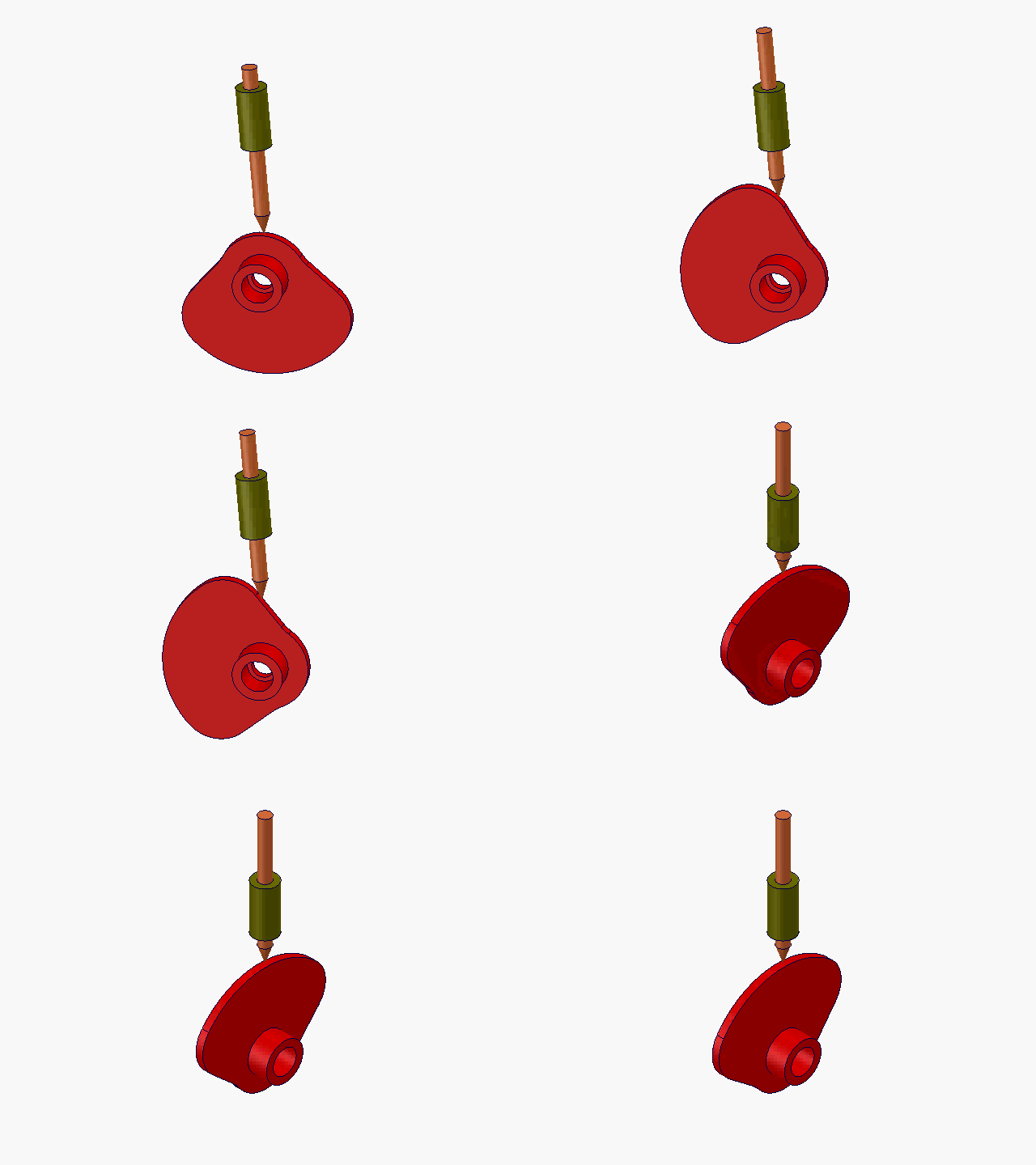
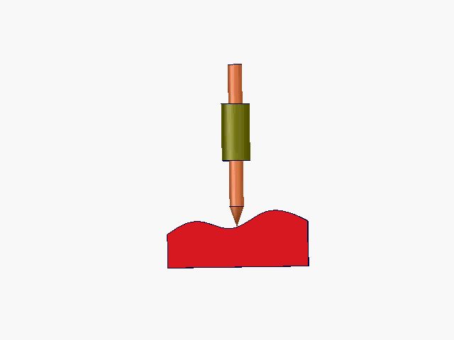
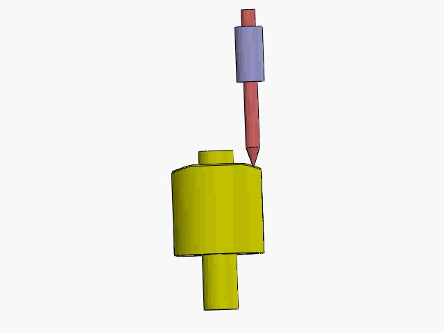
The cams are classified according to their shapes: disc cams, moving cams, and cylindrical cams.

Disc Cams

Moving Cams

Cylindrical Cams
Cylindrical cams
Also, we can classify them according to the end of the follower: tip follower, roller follower, and flat bottom follower.
Since the contact between the tip follower and the cam is point contact, its stress is high and its wear is fast, which is not suitable for low-speed cam mechanism with great impact. The roller follower can overcome these disadvantages. At the same time, in order to improve the transmission efficiency, we can also introduce flat-bottomed followers with the bottom plane perpendicular to the direction of force on the follower.
The drive elements we considered earlier are in the form of direct-action, which can also be in the form of oscillation. In the former case, we call it a direct-acting follower, and in the latter case we call it an oscillating follower.
We can also have the center of rotation of the cam not in the straight line of the follower's motion, which we call offset, and correspondingly, if the center of rotation is in the straight line of the follower's motion, we can call it counter-centered.
In addition, we can also consider the method of maintaining the locking relationship of the high sub, dividing the mechanism into geometric locking as well as force locking.
When we combine cam shape, follower end, and follower motion form, we can get the name of the mechanism we design, such as: tip straight follower disc cam (follower cam relative position + follower end + follower motion form + cam shape + cam)
Pressure angle of CNC machining
The pressure angle is the angle between the drive force and the speed of the follower movement. The larger the pressure angle is, the smaller the part of the driving force in the velocity direction, i.e., the useful part of the force F', and the larger the harmful part of the force F", the smaller the action of the cam on the follower, and when it is small to a certain extent, the cam cannot push it up, and self-locking occurs at this time.
How to design CNC machining?
There are two main methods for designing CNC machining, one is the graphical method and the other is the analytical method. The former is simpler and only requires a line drawing of the required pushing motion, and then the corresponding profile curve is obtained according to the angle-process relationship provided by the line drawing, which is not very accurate, while the latter is derived by means of calculation, which is relatively complicated and suitable for designing cam mechanisms with high accuracy requirements.
Conclusion
We offer a variety of CNC machining services including CNC milling, CNC routing, and CNC turning. Here is the definitive list of CNC machine services near your location as rated by your neighborhood community. Want to see who made the cut?


