Injection molding tolerances ensure the precision of plastic parts. Why are they so crucial? Without accurate tolerances, parts might not fit or function correctly. In this post, you'll learn the importance of these tolerances, factors affecting them, and how to optimize for best results.
What are Injection Molding Tolerances?
Injection molding tolerances refer to the allowable variations in part dimensions and features. They're specified by designers and engineers to ensure components fit and function as intended.
Tolerances are critical in injection molding. Even slight deviations can cause assembly issues or affect product performance. Specifying the right tolerances helps maintain part quality and consistency.To learn more about common issues that can affect tolerances, check out our guide on injection molding defects and how to solve them.
Types of Injection Molding Tolerances
There are several types of tolerances to consider in injection molding:
Dimensional Tolerances +/- mm
| Commercial Tolerance | Precision Higher Cost |
|
|
|
|
|
| Dimension | 1 to 20 (+/-mm) | 21 to 100 (+/-mm) | 101 to 160 (+/-mm) | for each 20mm over 160 add | 1 to 20 (+/-mm) | 21 to 100 (+/-mm) | over 100 |
| ABS | 0.100 | 0.150 | 0.325 | 0.080 | 0.050 | 0.100 |
|
| ABS/PC Blend | 0.100 | 0.150 | 0.325 | 0.080 | 0.050 | 0.100 |
|
| GPS | 0.075 | 0.150 | 0.305 | 0.100 | 0.050 | 0.080 |
|
| HDPE | 0.125 | 0.170 | 0.375 | 0.100 | 0.075 | 0.110 |
|
| LDPE | 0.125 | 0.170 | 0.375 | 0.100 | 0.075 | 0.110 |
|
| Mod PPO/PPE | 0.100 | 0.150 | 0.325 | 0.080 | 0.050 | 0.100 |
|
| PA | 0.075 | 0.160 | 0.310 | 0.080 | 0.030 | 0.130 |
|
| PA 30% GF | 0.060 | 0.120 | 0.240 | 0.080 | 0.030 | 0.100 |
|
| PBT 30% GF | 0.060 | 0.120 | 0.240 | 0.080 | 0.030 | 0.100 | project review |
| PC | 0.060 | 0.120 | 0.240 | 0.080 | 0.030 | 0.100 | required for all |
| PC 20% Glass | 0.050 | 0.100 | 0.200 | 0.080 | 0.030 | 0.080 | materials |
| PMMA | 0.075 | 0.120 | 0.250 | 0.080 | 0.050 | 0.070 |
|
| POM | 0.075 | 0.160 | 0.310 | 0.080 | 0.030 | 0.130 |
|
| PP | 0.125 | 0.170 | 0.375 | 0.100 | 0.075 | 0.110 |
|
| PP 20% Talc | 0.125 | 0.170 | 0.375 | 0.100 | 0.075 | 0.110 |
|
| PPS 30% GF | 0.060 | 0.120 | 0.240 | 0.080 | 0.030 | 0.100 |
|
| SAN | 0.100 | 0.150 | 0.325 | 0.080 | 0.050 | 0.100 |
|
Straightness/flatness tolerances: These deal with the warpage of flat surfaces. Factors like gate location, uniform cooling, and material selection can minimize warping. For more information on preventing warping, visit our article on warping in injection molding.
Straightness / Flatness Tolerances
| Commercial Tolerance | Precision Higher Cost |
|
|
| Dimensions | 0-100 (+/-mm) | 101-160 (+/-mm) | 0-100 (+/-mm) | 101-160 (+/-mm) |
| ABS | 0.380 | 0.800 | 0.250 | 0.500 |
| ABS/PC Blend | 0.380 | 0.800 | 0.250 | 0.500 |
| Acetal | 0.300 | 0.500 | 0.150 | 0.250 |
| Acrylic | 0.180 | 0.330 | 0.100 | 0.100 |
| GPS | 0.250 | 0.380 | 0.180 | 0.250 |
| Mod PPO/PPE | 0.380 | 0.800 | 0.250 | 0.250 |
| PA | 0.300 | 0.500 | 0.150 | 0.250 |
| PA 30% GF | 0.150 | 0.200 | 0.080 | 0.100 |
| PBT 30% GF | 0.150 | 0.200 | 0.080 | 0.100 |
| PC | 0.150 | 0.200 | 0.080 | 0.100 |
| Polycarbonate, 20% Glass | 0.130 | 0.180 | 0.080 | 0.100 |
| Polyethylene | 0.850 | 1.500 | 0.500 | 0.850 |
| Polypropylene | 0.850 | 1.500 | 0.500 | 0.850 |
| Polypropylene, 20% Talc | 0.850 | 1.500 | 0.500 | 0.850 |
| PPS 30% GF | 0.150 | 0.200 | 0.080 | 0.100 |
| SAN | 0.380 | 0.800 | 0.250 | 0.500 |
Hole Diameter Tolerances +/- mm
| Commercial Tolerance | Precision Higher Cost |
|
|
|
|
|
|
| Dimension | 0-3 (+/-mm) | 3.1-6 (+/-mm) | 6.1-14 (+/-mm) | 14-40 (+/-mm) | 0-3 (+/-mm) | 3.1-6 (+/-mm) | 6.1-14 (+/-mm) | 14-40 (+/-mm) |
| ABS | 0.050 | 0.050 | 0.080 | 0.100 | 0.030 | 0.030 | 0.050 | 0.050 |
| ABS/PC | 0.050 | 0.050 | 0.080 | 0.100 | 0.030 | 0.030 | 0.050 | 0.050 |
| GPS | 0.050 | 0.050 | 0.050 | 0.090 | 0.030 | 0.030 | 0.040 | 0.050 |
| HDPE | 0.050 | 0.080 | 0.100 | 0.150 | 0.030 | 0.050 | 0.050 | 0.080 |
| LDPE | 0.050 | 0.080 | 0.100 | 0.150 | 0.030 | 0.050 | 0.050 | 0.080 |
| PA | 0.050 | 0.080 | 0.080 | 0.130 | 0.030 | 0.040 | 0.050 | 0.080 |
| PA30% GF | 0.050 | 0.050 | 0.080 | 0.080 | 0.030 | 0.040 | 0.050 | 0.050 |
| PBT30% GF | 0.050 | 0.050 | 0.080 | 0.080 | 0.030 | 0.040 | 0.050 | 0.050 |
| PC | 0.050 | 0.050 | 0.080 | 0.080 | 0.030 | 0.040 | 0.050 | 0.050 |
| PC 20% GF | 0.050 | 0.050 | 0.080 | 0.080 | 0.030 | 0.040 | 0.050 | 0.050 |
| PMMA | 0.080 | 0.080 | 0.100 | 0.130 | 0.030 | 0.050 | 0.050 | 0.080 |
| POM | 0.050 | 0.080 | 0.080 | 0.130 | 0.030 | 0.040 | 0.050 | 0.080 |
| PP | 0.050 | 0.080 | 0.100 | 0.150 | 0.030 | 0.050 | 0.050 | 0.080 |
| PP, 20% Talc | 0.050 | 0.080 | 0.100 | 0.150 | 0.030 | 0.050 | 0.050 | 0.080 |
| PPS 30% Glass | 0.050 | 0.050 | 0.080 | 0.080 | 0.030 | 0.040 | 0.050 | 0.050 |
| SAN | 0.050 | 0.050 | 0.080 | 0.100 | 0.030 | 0.030 | 0.050 | 0.050 |
Blind Hole Depths Tolerances +/- mm
| Commercial Tolerance | Precision Higher Cost |
|
|
|
|
| Dimension | 1-6 (+/-mm) | 6.1-14 (+/-mm) | Over 14 (+/-mm) | 1-6 (+/-mm) | 6.1-14 (+/-mm) | Over 14 (+/-mm) |
| ABS | 0.080 | 0.100 | 0.130 | 0.050 | 0.050 | 0.080 |
| ABS/PC Blend | 0.080 | 0.100 | 0.130 | 0.050 | 0.050 | 0.080 |
| GPS | 0.090 | 0.100 | 0.130 | 0.050 | 0.050 | 0.080 |
| HDPE | 0.100 | 0.120 | 0.150 | 0.050 | 0.080 | 0.100 |
| LDPE | 0.100 | 0.120 | 0.150 | 0.050 | 0.080 | 0.100 |
| PA | 0.100 | 0.100 | 0.130 | 0.050 | 0.080 | 0.100 |
| PA, 30% GF | 0.050 | 0.080 | 0.100 | 0.050 | 0.050 | 0.080 |
| PBT, 30% GF | 0.050 | 0.080 | 0.100 | 0.050 | 0.050 | 0.080 |
| PC, 20% GF | 0.050 | 0.080 | 0.100 | 0.050 | 0.050 | 0.080 |
| PMMA | 0.100 | 0.100 | 0.130 | 0.050 | 0.080 | 0.100 |
| Polycarbonate | 0.050 | 0.080 | 0.100 | 0.050 | 0.050 | 0.080 |
| POM | 0.100 | 0.100 | 0.130 | 0.050 | 0.080 | 0.100 |
| PP | 0.100 | 0.120 | 0.150 | 0.050 | 0.080 | 0.100 |
| PP, 20% Talc | 0.100 | 0.120 | 0.150 | 0.050 | 0.080 | 0.100 |
| PPO/PPE | 0.080 | 0.100 | 0.130 | 0.050 | 0.050 | 0.080 |
| PPS, 30% GF | 0.050 | 0.080 | 0.100 | 0.050 | 0.050 | 0.080 |
| SAN | 0.080 | 0.100 | 0.130 | 0.050 | 0.050 | 0.080 |
Concentricity/Ovality Tolerances +/- mm
| Commercial Tolerance | Precision Higher Cost |
| Dimension | up to 100 (+/-mm) | up to 100 (+/-mm) |
| ABS | 0.230 | 0.130 |
| ABS/PC Blend | 0.230 | 0.130 |
| GPS | 0.250 | 0.150 |
| HDPE | 0.250 | 0.150 |
| LDPE | 0.250 | 0.150 |
| PA | 0.250 | 0.150 |
| PA, 30% GF | 0.150 | 0.100 |
| PBT, 30% GF | 0.150 | 0.100 |
| PC | 0.130 | 0.080 |
| PC, 20% GF | 0.130 | 0.080 |
| PMMA | 0.250 | 0.150 |
| POM | 0.250 | 0.150 |
| PP | 0.250 | 0.150 |
| PP, 20% Talc | 0.250 | 0.150 |
| PPO/PPE | 0.230 | 0.130 |
| PPS, 30% GF | 0.130 | 0.080 |
| SAN | 0.230 | 0.130 |
Commercial vs. Fine Tolerances
Injection molding tolerances can be broadly categorized into two types:
Commercial tolerances: These are less precise but more economical. They're suitable for non-critical applications and allow for greater dimensional variations.
Fine (precision) tolerances: These provide tighter control over part dimensions. They require high-quality molds and strict process control, making them more expensive.
The choice between commercial and fine tolerances depends on the specific application and functional requirements of the part.
To learn more about this, check out our guide on types of gates for injection molding.
Importance of Injection Molding Tolerances
Injection molding tolerances play a vital role in the production of high-quality plastic parts. They ensure that components meet the required specifications and perform as intended. Let's explore why tolerances are so crucial and what happens when they're not properly controlled.
Why are Tolerances Crucial?
Ensuring Part Functionality and Fit
Tolerances guarantee that injection molded parts fit and function correctly. They allow for slight variations in dimensions while still maintaining the part's integrity. Without proper tolerances, components may not mate properly during assembly or operate as designed.
Imagine trying to snap together two plastic housing halves. If the tolerances are too loose, there will be gaps and rattling. If they're too tight, the parts won't fit at all. Precise tolerances ensure a secure, seamless fit.
Impact on Assembly and Performance
Injection molded parts often work in conjunction with other components. They may need to accommodate fasteners, align with mating parts, or allow for the smooth operation of moving elements. Tolerances are essential for ensuring that all these interactions occur flawlessly.
Take a plastic gear as an example. If the gear's dimensions are out of tolerance, it may not mesh correctly with its counterpart. This could lead to decreased efficiency, excessive wear, or even complete failure of the mechanism.
Consequences of Poor Tolerance Control
Assembly Errors
When tolerances are not held to specification, assembly becomes a challenge. Parts may not align, mate, or fasten as intended. This leads to delays, rework, and increased production costs.
Consider an electronic device housing. If the bosses for the screws are out of tolerance, the device may not assemble properly. The screws could strip, or the housing might not close securely. These issues result in wasted time and materials.
Functional and Aesthetic Defects
Poor tolerance control can lead to functional problems in the final product. Misaligned or ill-fitting parts can cause:
Leaks
Gaps
Uneven surfaces
Excessive wear
Malfunctions
These defects not only affect the product's performance but also detract from its appearance. Visible gaps, mismatched edges, or wobbling components can make a product look cheap and unreliable.To learn more about common injection molding defects and how to prevent them, check out our comprehensive guide on injection molding defects.
One particularly common issue related to poor tolerance control is warping. This can significantly affect the fit and function of parts. For more information on this topic, visit our article on warping in injection molding.
Another aesthetic issue that can arise from poor tolerance control is the appearance of sink marks. These can be particularly problematic in visible areas of the part. To learn more about sink marks and how to prevent them, see our guide on sink marks in injection molding.
Factors Affecting Injection Molding Tolerances
Achieving tight tolerances in injection molding requires careful consideration of several factors. From part design to material selection, tooling, and process control, each element plays a crucial role. Let's dive into the key factors that influence injection molding tolerances.
Part Design
Overall Size
The overall size of the part has a significant impact on tolerances. Larger parts tend to experience more shrinkage during cooling, making it harder to maintain tight tolerances. Designers need to account for this when specifying dimensions and tolerances.
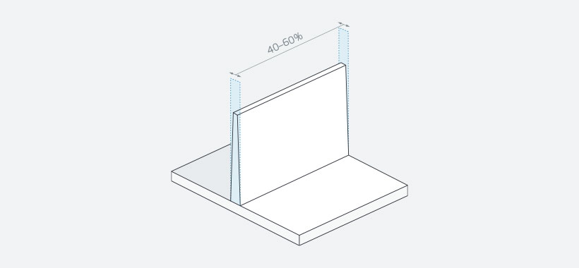
Wall Thickness
Consistent wall thickness is essential for controlling tolerances. Variations in wall thickness can lead to uneven cooling and shrinkage, resulting in warpage and dimensional inaccuracies. It's crucial to maintain uniform wall thickness throughout the part.
Draft Angles
Draft angles are necessary for easy ejection of the part from the mold. However, they can also affect tolerances. Steeper draft angles may be required for deeper features, which can impact the dimensions of the part. Designers must strike a balance between ease of ejection and maintaining tolerances.
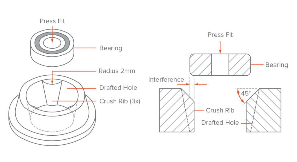
Bosses
Bosses are raised features used for mounting or reinforcement. They can be challenging from a tolerance perspective. Thick bosses can lead to sink marks and warpage due to slower cooling. Designers should follow best practices for boss design, such as maintaining consistent wall thickness and avoiding abrupt changes in thickness. To learn more about preventing sink marks, visit our article on sink marks in injection molding.
Material Selection
Shrinkage Rates of Different Plastics
Different plastic materials have varying shrinkage rates. Some materials, like polypropylene, have higher shrinkage than others, such as ABS. Designers must consider the shrinkage rate of the chosen material when specifying tolerances. Mold designers also need to account for shrinkage when creating the tool.
| Material | Shrinkage Range |
| ABS | 0.7–1.6 |
| PC/ABS | 0.5–0.7 |
| Acetal/POM (Delrin®) | 1.8–2.5 |
| ASA | 0.4–0.7 |
| HDPE | 1.5–4 |
| HIPS | 0.2–0.8 |
| LDPE | 2–4 |
| Nylon 6/6 | 0.7–3 |
| Nylon 6/6 Glass Filled (30%) | 0.5-0.5 |
| PBT | 0.5–2.2 |
| PBT Glass Filled (30%) | 0.2–1 |
| PEEK | 1.2–1.5 |
| PEEK Glass Filled (30%) | 0.4–0.8 |
| PEI (Ultem®) | 0.7–0.8 |
| PET | 0.2–3 |
| PMMA (Acrylic) | 0.2–0.8 |
| PC | 0.7-1 |
| PC Glass Filled (20–40%) | 0.1–0.5 |
| Polyethylene Glass Filled (30%) | 0.2–0.6 |
| Polypropylene Homopolymer | 1–3 |
| Polypropylene Copolymer | 2–3 |
| PPA | 1.5–2.2 |
| PPO | 0.5–0.7 |
| PPS | 0.6–1.4 |
| PPSU | 0.7-0.7 |
| Rigid PVC | 0.1–0.6 |
| SAN (AS) | 0.3–0.7 |
| TPE | 0.5–2.5 |
| TPU | 0.4–1.4 |
Table : [Shrinkage Rates]
Impact of Fillers and Additives on Shrinkage
Fillers and additives can also influence shrinkage and tolerances. For example, glass-filled plastics tend to have lower shrinkage rates than unfilled versions. However, the orientation of the fibers can lead to anisotropic shrinkage, where the part shrinks differently in different directions. It's important to consider the effects of fillers and additives when selecting materials and setting tolerances.
Tooling
Mold Design and Cooling Channels
Proper mold design is crucial for maintaining tolerances. The placement and design of cooling channels can greatly impact part dimensions. Uneven cooling can cause warpage and dimensional variation. Mold designers must ensure that cooling is uniform throughout the tool to minimize these issues.
Gate and Ejector Pin Locations
The location of gates and ejector pins can also affect tolerances. Gates are the entry points for the molten plastic, and their placement can influence the flow and cooling of the material. Ejector pins are used to remove the part from the mold, and their location and design can impact the part's final dimensions. Careful consideration of gate and ejector pin placement is necessary to maintain tolerances. For more information on gate types and their impact, see our guide on types of gates for injection molding.
Process Controls
Injection Pressure
Injection pressure is a critical process parameter that affects tolerances. Too high of an injection pressure can lead to overpacking, causing dimensional changes and stress within the part. Too low of a pressure can result in incomplete filling and dimensional inconsistencies. Finding the optimal injection pressure is key to maintaining tolerances.
Holding Time
Holding time refers to the duration that pressure is maintained after the initial injection. Adequate holding time is necessary to allow the part to solidify and maintain its dimensions. Insufficient holding time can lead to sink marks and dimensional changes. Conversely, excessive holding time can cause over-packing and stress. Optimizing holding time is essential for achieving tight tolerances.
Mold Temperature
Mold temperature plays a significant role in controlling tolerances. The temperature of the mold affects the cooling rate of the plastic and, consequently, the shrinkage and warpage of the part. Maintaining consistent mold temperature is crucial for achieving repeatable dimensions. Mold temperature should be carefully monitored and controlled to ensure stable tolerances.
Designing for Optimal Injection Molding Tolerances
Design for Manufacturability (DFM) Principles
Adhering to DFM principles ensures that parts are easy to manufacture. This minimizes errors and improves tolerance control. Good design reduces costs and speeds up production.
Uniform Wall Thickness
Maintaining uniform wall thickness is crucial. Inconsistent walls cause warping and sinking. Aim for even thickness throughout the part. This enhances dimensional stability.
Diagram: Effects of Wall Thickness
Proper Draft Angles
Draft angles help in the easy ejection of parts from molds. Without sufficient draft, parts may stick and distort. Generally, a 1-2 degree draft is recommended for most parts. For a detailed explanation of draft angles and their importance, visit our article on draft angles in injection molding.
Core and Cavity Design Considerations
Designing the core and cavity correctly is vital. Ensure there are no undercuts that complicate molding. Proper design enhances mold life and part accuracy.
Table: Core and Cavity Design Tips
| Consideration | Impact |
| Avoid Undercuts | Simplifies mold design |
| Use Uniform Surfaces | Ensures even cooling |
| Optimize Ejection Points | Prevents part deformation |
Parting Line Placement
The parting line affects the final part's aesthetics and functionality. Place it in a non-critical area to avoid visible defects. Proper placement ensures clean separation and minimal flash. For more information on parting line considerations, see our guide on parting lines in injection molding.
Material Selection and Tolerances
Common Injection Molding Materials and Their Shrinkage Rates
Amorphous vs. Semi-Crystalline Plastics
Amorphous plastics, like ABS, shrink less than semi-crystalline plastics. Semi-crystalline plastics, like polypropylene, have higher shrinkage rates. This difference is crucial for achieving tight tolerances.
To learn more about polypropylene injection molding and its unique properties, visit our article on polypropylene injection molding.
Impact of Fillers and Additives on Shrinkage and Tolerances
Fillers and additives can significantly affect shrinkage. For example, glass fibers reduce shrinkage and enhance stability. This improves the precision of molded parts. Plasticizers increase flexibility but may alter shrinkage rates.
Examples of Common Additives
Glass Fibers: Reduces shrinkage, improves strength.
Plasticizers: Increases flexibility, may change shrinkage.
Flame Retardants: Enhances fire resistance without affecting shrinkage much.
Mold Flow Analysis for Predicting Shrinkage
Mold flow analysis helps predict how materials will shrink. This simulation tool allows designers to visualize material flow and cooling. It aids in optimizing mold design to achieve desired tolerances.
Steps in Mold Flow Analysis
Model Creation: Develop a 3D model of the part.
Simulation Setup: Input material properties and processing conditions.
Run Simulation: Analyze flow, cooling, and shrinkage patterns.
Review Results: Adjust design based on simulation data.
Using mold flow analysis, manufacturers can foresee potential issues. This ensures accurate tolerances and high-quality parts. For advanced materials with specific shrinkage characteristics, such as PEEK, consider reading our article on PEEK injection molding.
Tooling and Injection Molding Tolerances
Mold Design and Its Impact on Tolerances
Mold design directly influences injection molding tolerances. A well-designed mold ensures parts are precise and consistent. Poor design leads to dimensional inaccuracies and defects. For insights into designing key mold components, check out our guide on designing the hot runner plate in injection molding.
Cooling Channel Placement and Uniform Cooling
Proper cooling channel placement is crucial. Uniform cooling prevents warping and shrinkage. Channels should be strategically placed for even heat dissipation.
Gate and Ejector Pin Locations
Gate and ejector pin locations affect part quality. Gates should be in thick-walled areas to ensure complete packing. Ejector pins must be placed to avoid part deformation.
Table: Gate and Ejector Pin Tips
| Consideration | Impact |
| Gate in Thick Areas | Ensures proper material flow |
| Strategic Pin Placement | Prevents warping and deformation |
For a detailed look at ejector pins and their crucial role, visit our guide on ejector pins in injection molding.
Mold Material and Machining Tolerances
The choice of mold material impacts machining tolerances. High-quality materials allow for tighter tolerances. Precision machining ensures the mold maintains its accuracy over time.
List: Mold Material Characteristics
High hardness: Reduces wear
Good thermal conductivity: Ensures uniform cooling
Corrosion resistance: Prolongs mold life
Process Control for Maintaining Tolerances
Importance of Consistent Process Parameters
Consistent process parameters are crucial in injection molding. They ensure part quality and maintain tight tolerances. Variations in parameters can lead to defects and dimensional inaccuracies.
Injection Pressure and Its Effect on Tolerances
Injection pressure directly affects material flow. High pressure ensures complete cavity filling. Inconsistent pressure can cause voids and shrinkage, impacting tolerances. To learn more about issues related to incomplete filling, check out our guide on short shots in injection molding.
Holding Time and Mold Temperature
Proper holding time prevents material backflow. It ensures parts retain their shape and dimensions. Incorrect holding time leads to warping and sink marks. Mold temperature control is equally important. Consistent temperature ensures uniform cooling and reduces internal stresses.
Table: Optimal Holding Times and Temperatures
| Parameter | Optimal Range |
| Holding Time | 5-15 seconds |
| Mold Temperature | 75-105°C |
Scientific Molding Approach
Scientific molding optimizes the injection process. It uses data to control variables like pressure, time, and temperature. This approach ensures repeatability and consistency, maintaining tight tolerances across production runs.
Steps in Scientific Molding
Data Collection: Gather process data.
Analysis: Identify optimal settings.
Implementation: Apply settings in production.
Monitoring: Continuously monitor and adjust.
Measurement and Inspection Techniques
Visual Inspection
Visual inspection is the first step in quality control. It helps identify surface defects and warpage quickly. Inspectors look for scratches, dents, and other imperfections.
Diagram: Common Surface 
Manual Measurement Tools
Calipers and Micrometers
Calipers and micrometers are essential for manual measurement. They provide precise readings of dimensions. Use them to measure thickness, diameter, and depth.
Best Practices for Manual Measurement
Use a consistent method to ensure accuracy. Zero the caliper before each use. Apply gentle pressure to avoid deforming the part.
Table: Manual Measurement Best Practices
| Tool | Usage Tip |
| Calipers | Zero before use |
| Micrometers | Apply gentle pressure |
Automated Measurement Systems
Coordinate Measuring Machines (CMMs)
CMMs provide high accuracy for complex parts. They use probes to measure coordinates of the part’s surface. This method is ideal for detailed dimensional analysis.
Vision Systems
Vision systems use cameras and sensors. They capture images and analyze dimensions automatically. These systems are fast and efficient for high-volume inspections.
First Article Inspection (FAI)
FAI is a comprehensive inspection of the first part produced. It ensures the initial part meets design specifications. FAI involves measuring all dimensions and comparing them to the design.
Comprehensive Dimensional Analysis
FAI checks every critical dimension. This analysis verifies that the part conforms to the design.
Ensuring Initial Part Accuracy
Accurate first articles set the standard for production. They help identify potential issues early. This ensures consistent quality in subsequent parts.
Table: FAI Checklist
| Step | Description |
| Measure Dimensions | Compare to design specs |
| Inspect Surface | Check for defects |
| Verify Materials | Ensure correct material used |
Common Challenges and Solutions
Dealing with Warpage and Shrinkage
Design Adjustments and Material Choices
Warpage and shrinkage are common issues. Adjusting the design can help. Use consistent wall thickness to minimize warpage. Choose materials with low shrinkage rates for better dimensional stability.
Table: Materials and Shrinkage Rates
| Material | Shrinkage Rate |
| ABS | Low |
| Polypropylene | High |
| Nylon | Moderate |
Process Modifications
Modifying the injection process can reduce warpage. Use uniform cooling to prevent uneven shrinkage. Adjust injection pressure to ensure complete filling of the mold.
Managing Tolerance Stack-ups
Cumulative Effect of Dimensional Deviations
Tolerance stack-ups occur when small deviations add up. This can affect the fit and function of assembled parts. Understanding cumulative effects is key to managing them.
Techniques to Minimize Stack-up Issues
Several techniques help minimize stack-ups. Use tighter tolerances on critical dimensions. Apply statistical process control (SPC) to monitor production. Design for assembly to ensure parts fit together properly.
Table: Techniques for Managing Tolerance Stack-ups
| Technique | Benefit |
| Tighter Tolerances | Reduces cumulative deviations |
| Statistical Process Control (SPC) | Monitors and controls quality |
| Design for Assembly | Ensures proper part fit |
Conclusion
Understanding and controlling injection molding tolerances is crucial. Precise tolerances ensure parts fit and function properly. Design, material selection, and process control all impact tolerances. Addressing issues like warpage and shrinkage is essential for quality.
Partnering with experienced injection molding providers offers many benefits. They bring expertise and advanced technology. This ensures high-quality, reliable parts. Working with professionals saves time and reduces costs.
In summary, proper control of injection molding tolerances leads to better products. This is vital for successful manufacturing and customer satisfaction.


