Injection molding requires precision, and one critical factor is often overlooked: wall thickness. How does this affect product quality and cost?
Wall thickness in plastic parts impacts strength, cooling time, and material flow. Improper thickness leads to defects like warping or sink marks.
In this post, you'll learn essential guidelines for designing optimal wall thickness for common plastics. We'll cover best practices, recommended ranges for materials, and key factors influencing your choices.

What is Wall Thickness in Injection Molding?
Wall thickness refers to the distance between two parallel surfaces of an injection molded part. It's a crucial design parameter affecting the part's structural integrity, appearance, and manufacturability.
Significance of Wall Thickness in Product Design
Proper wall thickness design is vital for successful injection molding. It impacts several key aspects of product development and manufacturing:
Reduced Raw Material Usage
Optimal wall thickness helps minimize material consumption. This leads to:
Improved Part Quality
Well-designed wall thickness contributes to better part quality by:
Minimizing defects like sink marks, warpage, and voids
Enhancing structural strength and rigidity
Improving surface finish and dimensional accuracy
Faster Production Speed
Appropriate wall thickness can significantly speed up production:
Shorter cooling times, reducing overall cycle time
Improved material flow, facilitating easier mold filling
Less post-processing required, streamlining production
Recommended Wall Thickness for Common Plastics
Wall thickness recommendations vary depending on the specific plastic material. Generally, they range from 0.020 inches to 0.500 inches. These guidelines ensure optimal part performance and manufacturability.
Plastic Wall Thickness Chart for Commonly Used Thermoplastics
For different plastics, ideal wall thicknesses fall within certain ranges. Below is a chart showing the recommended thicknesses for commonly used materials in injection molding processes:
| Material | Recommended Wall Thickness (in) | Recommended Wall Thickness (mm) |
| ABS | 0.045 – 0.140 | 1.14 – 3.56 |
| PC+ABS | 0.035 – 0.140 | 0.89 – 3.56 |
| Acetal | 0.030 – 0.120 | 0.76 – 3.05 |
| Acrylic | 0.025 – 0.500 | 0.64 – 12.7 |
| Nylon | 0.030 – 0.115 | 0.76 – 2.92 |
| Polycarbonate (PC) | 0.040 – 0.150 | 1.02 – 3.81 |
| Polyethylene (PE) | 0.030 – 0.200 | 0.76 – 5.08 |
| Polypropylene (PP) | 0.025 – 0.150 | 0.64 – 3.81 |
| Polystyrene (PS) | 0.035 – 0.150 | 0.89 – 3.81 |
| Polyurethane | 0.080 – 0.750 | 2.03 – 19.05 |
Factors Influencing the Choice of Material
Choosing the right plastic for a part involves more than just selecting the correct wall thickness. Several factors affect the material choice, which ultimately determines the performance and longevity of the molded part.
Chemical and UV Resistance
Materials must withstand exposure to chemicals, solvents, and ultraviolet (UV) light. Plastics like ABS and PC+ABS offer moderate chemical resistance but can degrade under intense UV exposure. In contrast, Polypropylene (PP) and Acrylic maintain good UV resistance, making them suitable for outdoor applications.
Heat Resistance
Heat resistance is another critical consideration. Polycarbonate (PC) can handle higher temperatures compared to ABS, which deforms at lower heat levels. Nylon offers good heat resistance with the addition of fillers, while PE and PP excel in low to moderate temperature environments.
Strength and Flexibility
Material strength and flexibility dictate part durability under mechanical stress. ABS provides moderate strength with good impact resistance, while Nylon and PC+ABS are known for their higher tensile strength. For flexible parts, Polyurethane and Polypropylene are often the materials of choice.
Color and Opacity
The aesthetic requirements of the part will influence material selection. Some plastics, such as Acrylic and Polycarbonate, are preferred for their transparency and optical clarity. ABS and PP can easily be pigmented to achieve specific colors, while maintaining part uniformity.
Electromagnetic Compatibility
Certain applications require materials with specific electromagnetic properties. Polycarbonate and ABS blends (PC+ABS) are often used in electronics where electromagnetic interference (EMI) shielding is required, while materials like Nylon may be chosen for their insulating properties in electrical components.
Principles of Plastic Part Thickness Design
Uniform Wall Thickness Principle
Maintaining uniform wall thickness is crucial for optimal part performance:
Specific Thickness Guidelines
Different components require specific thickness ranges:
| Component | Recommended Thickness (mm) |
| Shell (thickness direction) | 1.2 - 1.4 |
| Side walls | 1.5 - 1.7 |
| Outer lens support surface | 0.8 |
| Inner lens support surface | ≥ 0.6 |
| Battery cover | 0.8 - 1.0 |
Gradual Thickness Transitions
Smooth transitions between varying thicknesses prevent defects:
Maintain slight thickness differences at thick-thin wall connections
Aim for 40-60% of adjacent wall thickness
Implement arc transitions at wall junctions
Material Flow and Fill Properties
Wall thickness affects material flow during injection:
Minimizing Wall Thickness
Balance functionality and material efficiency:
Set minimum thickness to 0.6-0.9mm
Aim for a general range of 2-5mm
Reduce thickness where possible to save material and lower costs
Considering Material Viscosity
Material properties influence thickness design:

Wall Thickness Design Based on Cost Principles
Relationship Between Cooling Time and Wall Thickness
Wall thickness significantly impacts cooling time, affecting production efficiency and costs:
Thicker walls require longer cooling periods
Extended cooling time reduces overall productivity
Increased cycle times lead to higher unit costs
Consider the following relationship:
| Wall Thickness Increase | Approximate Cooling Time Increase |
| 10% | 20% |
| 20% | 45% |
| 30% | 70% |
Minimizing Wall Thickness for Optimal Efficiency
Balancing functionality and efficiency requires careful consideration:
Functional Requirements:
Structural Integrity:
Cooling Optimization:
Quality Assurance:
By optimizing these factors, designers can:
Impact of Non-Uniform Wall Thickness
Non-uniform wall thickness in injection molding can lead to a range of issues affecting both product quality and manufacturing efficiency. These variations can cause defects, cooling imbalances, and difficulties during the molding process.
Cosmetic Defects
One of the most common problems resulting from non-uniform wall thickness is cosmetic defects. These imperfections affect the appearance and, in some cases, the structural integrity of the part.
Sink Marks: Thicker sections cool more slowly, causing the surface to sink inward, creating visible marks.
Warpage: Uneven shrinkage between thick and thin sections leads to part distortion, or warping, as different areas cool at different rates.
Cooling Rate Variations
Non-uniform thickness causes inconsistent cooling rates across the part. Thicker sections take longer to cool, while thinner areas solidify faster. This imbalance can lead to defects and requires extended cycle times to ensure all areas are properly cooled, reducing overall production efficiency.
Gating Challenges
Gating in injection molding becomes more complex when dealing with non-uniform walls. Molten material may have difficulty flowing into thinner sections after filling thicker areas. This flow interruption can cause incomplete filling or inconsistent packing, resulting in defects and underperformance.
Appearance Issues
Non-uniform thickness often results in appearance problems such as:
Flow Lines: Variations in thickness cause irregular flow patterns, creating visible streaks or lines on the part surface.
Difficulty Maintaining Cavity Contact: Thicker sections may not maintain full cavity contact during cooling, making it hard to achieve the desired surface finish or texture.
Shear Stress and Fiber Orientation
Non-uniform wall thickness also impacts the internal structure of the molded part, particularly in fiber-reinforced plastics. Thinner areas experience higher shear stress, leading to different fiber orientations. This variation in fiber alignment affects the part’s strength and can contribute to warping or failure under load.
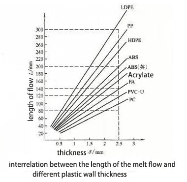
Calculating Wall Thickness using Flow Ratio (L/T)
Definition of Flow Ratio (L/T)
The flow ratio (L/T) represents the relationship between flow path length (L) and wall thickness (T) in injection molding. It indicates how far molten plastic can travel within a given wall thickness.
Importance of L/T Ratio
L/T ratio plays a crucial role in:
Determining optimal injection point locations
Establishing achievable wall thicknesses
Balancing part design with manufacturability
A higher L/T ratio allows for thinner walls or longer flow paths, influencing overall part design and production efficiency.
Factors Influencing L/T Ratio Calculation
Several variables affect the L/T ratio:
Material temperature
Mold temperature
Surface finish
Resin viscosity
Injection pressure
These factors interact complexly, making precise calculations challenging. Experienced molders often rely on approximate ranges and practical knowledge.
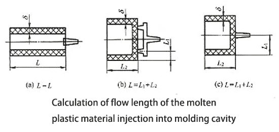
Example L/T Ratio Calculation
Consider a PC part with:
L/T (total) = L1/T1 (runner) + L2/T2 (product) = 100/5 + 200/2 = 120
This exceeds the typical L/T ratio for PC (90), indicating potential molding difficulties.
Improving Moldability
To enhance moldability:
Adjust gate positioning:
Modify wall thickness:
These adjustments optimize the molding process, ensuring better part quality and production efficiency.
Other Considerations for Injection Molding Wall Thickness Design
Designing the correct wall thickness for injection-molded parts involves more than just basic guidelines. Several factors influence the final design, impacting both performance and production efficiency.
Basic Structure and Dimensional Requirements
Product design fundamentals significantly influence wall thickness:
Overall shape and size dictate minimum thickness requirements
Complex geometries may necessitate varying wall thicknesses
Structural integrity needs often determine minimum thickness values
Designers must balance these factors with manufacturability concerns to optimize part performance and production efficiency.
Properties and Characteristics of Raw Materials
Material selection plays a crucial role in wall thickness design:
| Material Property | Impact on Wall Thickness |
| Melt Flow Index | Higher MFI allows for thinner walls |
| Shrinkage Rate | Affects dimensional accuracy and warpage |
| Thermal Conductivity | Influences cooling time and cycle efficiency |
Understanding these properties helps designers choose appropriate wall thicknesses for specific materials.
Mold Design and Injection Molding Process Parameters
Mold and process considerations affect wall thickness decisions:
Gate location and size impact flow patterns and thickness requirements
Cooling system design influences achievable wall thicknesses
Injection pressure and speed limitations may dictate minimum thicknesses
Collaborating with mold designers and process engineers ensures optimal wall thickness for manufacturability.
Assembly and Usage Requirements
End-use considerations must factor into wall thickness design:
Snap fits and living hinges require specific thickness-to-length ratios
Load-bearing areas may need reinforced wall thicknesses
Thermal or electrical insulation needs can influence thickness choices
Designers should consider the entire product lifecycle when determining appropriate wall thicknesses.
Conclusion
In designing for injection molding, maintaining optimal wall thickness is key. It impacts strength, cooling time, and production efficiency. Following recommended guidelines for various materials ensures consistent results and reduces defects like sink marks or warping.
Working with an experienced manufacturer helps fine-tune wall thickness for specific project needs. They provide valuable insights into material behavior, tooling, and molding techniques.
Optimizing wall thickness balances cost, quality, and performance. It reduces material usage, shortens cooling time, and enhances part durability. Proper thickness design leads to efficient, high-quality production.


